Hi this is Team Merchant Navy Decoded !!!

Please fill the below form with your query and we will get back to you in next 12 hours.

Rest assured your data is safe with us !!!🙂

Ask Your Query

Main Engine Reversing in MAN B&W MC Engine: Working Principle, Reversing Mechanism & Sequence

A ship fitted with a Fixed Pitch Propeller (FPP) cannot change the direction of thrust by altering the propeller blade angle. To move the vessel astern, the main engine itself must rotate in the opposite direction. This operation is known as main engine reversing.

Among low-speed two-stroke marine diesel engines, the MAN B&W MC engine uses a reliable mechanical camshaft reversing system. Instead of electronically changing fuel injection timing, the engine mechanically shifts the fuel pump cam followers while simultaneously changing the starting air sequence.

Main engine reversing is one of the most critical manoeuvring operations on board, enabling safe berthing, unberthing, anchoring, emergency stopping, canal transit, and navigation in confined waters.

Working Principle of Main Engine Reversing

When an Astern command is received from the bridge, the engine control system first reduces the engine speed to zero RPM. Once the engine has completely stopped, the reversing mechanism changes the timing of the engine components to suit reverse rotation.

The sequence is as follows:

  1. The engine is brought to a complete stop.
  2. Fuel pump (injection) timing is shifted to the astern position.
  3. Starting-air distributor timing is changed to the reverse firing order.
  4. Compressed starting air rotates the crankshaft in the opposite direction.
  5. Once sufficient speed is achieved, fuel injection begins and the engine continues running astern under its own power.

Note: on conventional camshaft-type engines (MC, RTA), the exhaust valve cam profile is symmetrical about bottom dead centre, so it does not need to be repositioned when reversing — only the fuel pump cam/follower and the starting-air distributor timing change. Electronically controlled engines (RT-flex, ME) do adjust exhaust valve timing electronically for each direction, since they have no fixed mechanical cam at all.

Although every reversible two-stroke engine follows this basic principle, the reversing mechanism differs between engine manufacturers.

Table of Contents

MAN B&W MC Engine Reversing

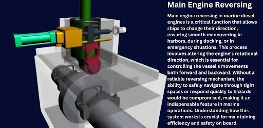
Main Engine Reversing

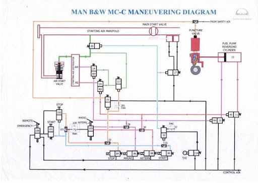
MAN B&W MC-C Maneuvring
Main Engine Reversing

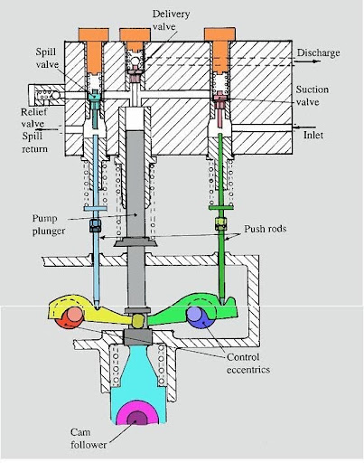
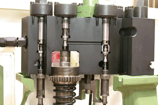
The MAN B&W MC engine retains a conventional camshaft carrying separate ahead and astern cam profiles for each fuel pump. Reversing is carried out not by moving the cam itself, but by shifting the fuel pump cam follower (roller) sideways from the ahead cam track onto the astern cam track. On most MC-series engines this shift is performed by an air-operated (pneumatic) cylinder fitted to each follower unit, triggered by the starting-air/control-air system once the engine has stopped; the roller only transfers across when the engine is turning, since the incline between the two cam tracks needs cam motion to carry it over.

At the same time, the engine-driven starting-air distributor is switched to the reverse firing sequence so that starting air is admitted to the correct cylinders in the correct order for astern rotation.

Reversing Sequence

  1. Engine is stopped.
  2. Air-operated cylinders shift the fuel pump cam followers from the ahead cam track to the astern cam track.
  3. The starting-air distributor changes to the reverse firing order.
  4. Limit switches/position indicators confirm correct follower and distributor positioning.
  5. Starting air rotates the engine astern.
  6. Fuel injection starts with the correct astern timing.

Advantages

  • Proven, robust mechanical design
  • No need to reposition the exhaust valve cam (symmetrical profile)
  • Well understood maintenance and troubleshooting procedures
  • Reliable across decades of service

The engine control system will not permit fuel admission unless the follower position and starting-air distributor position are correctly verified by the monitoring system.

Sulzer RTA Engine Reversing

Sulzer RT-flex Electronic Engine Reversing

Sulzer RTA Engine Reversing

The Sulzer RTA engine uses a hydraulic “lost-motion” reversing servomotor mounted directly on the camshaft to change fuel injection timing. The fuel pump cams are pressed onto sleeves that surround the camshaft; the servomotor (typically shared between a pair of adjacent cylinders) rotates these cam sleeves relative to the camshaft through a defined “lost motion” angle, re-timing the same physical cam for astern running instead of fitting a separate cam. As with the MC engine, the exhaust valve cam profile is symmetrical and does not need to be moved.

Reversing Sequence

  1. The engine stops completely.
  2. Hydraulic oil is directed to the reversing servomotor on the camshaft.
  3. The servomotor rotates the fuel pump cam sleeves through the lost-motion angle to the astern position.
  4. Fuel injection timing changes accordingly.
  5. The starting-air distributor changes to the reverse firing sequence.
  6. Position indicators verify successful cam movement.
  7. Starting air rotates the engine astern.
  8. Fuel injection begins after all safety checks are satisfied.

Advantages

  • Accurate fuel injection timing
  • Reliable hydraulic operation
  • Smooth reversing
  • Proven design for low-speed engines

Sulzer RT-flex Electronic Engine Reversing

Sulzer RT-flex Electronic Engine Reversing

Sulzer RT-flex Electronic Engine Reversing

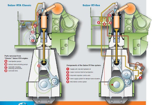
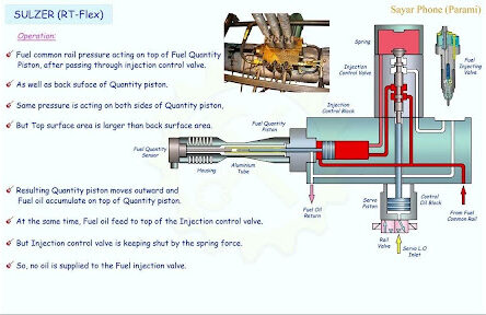
The Sulzer RT-flex engine represents a later generation of electronically controlled low-speed marine diesel engines. Unlike conventional camshaft engines, the RT-flex uses a common-rail system controlled by an Electronic Control Unit (ECU).

There are no mechanical reversing cams or hydraulic reversing servomotors.

Reversing Sequence

  1. Engine speed reduces to zero.
  2. ECU selects astern mode.
  3. Fuel injection timing is electronically adjusted.
  4. Exhaust valve timing is electronically controlled.
  5. Starting-air valves operate through electronically controlled solenoid valves.
  6. Sensors verify all operating parameters.
  7. Fuel injection begins only after every safety condition is fulfilled.

Advantages

  • Faster engine response
  • Precise fuel injection
  • Lower fuel consumption
  • Reduced maintenance
  • Improved engine efficiency
  • Better emission performance

Electronic control removes many mechanical components (camshaft, cam followers, reversing servomotors, mechanical starting-air distributor), making the reversing process simpler, quicker, and more reliable.

Safety Interlocks During Reversing

Before the engine is permitted to start astern, the control system verifies several critical conditions:

  • Engine speed must be 0 RPM.
  • Correct ahead or astern command selected.
  • Fuel injection timing correctly adjusted.
  • Starting-air distributor synchronized.
  • Hydraulic control pressure available (where applicable).
  • Cam follower or cam sleeve position confirmed.
  • Position sensors and microswitches functioning correctly.
  • Engine control system free from active safety trips.

Only after all these conditions are successfully verified does the control system permit fuel injection and engine starting.

Maintenance of Reversing Mechanism

Routine inspection and maintenance ensure reliable reversing performance.

Key maintenance points include:

  • Hydraulic servo units
  • Hydraulic oil quality
  • Fuel cam sleeves and cam followers
  • Starting-air distributor
  • Starting-air valves
  • Position sensors and microswitches
  • Solenoid valves
  • Hydraulic pipelines and seals
  • Control air system

Any sticking mechanism, hydraulic leakage, worn components or incorrect timing can lead to failed reversing, poor combustion, excessive exhaust temperatures and unsafe manoeuvring.

Conclusion

Main engine reversing is essential for ships equipped with Fixed Pitch Propellers, as the propeller itself cannot reverse thrust. Reversing is achieved by changing the timing of fuel injection, starting air and exhaust valve events.

Frequently Asked Questions (FAQs)

Ships with a Fixed Pitch Propeller (FPP) must reverse the main engine to generate astern thrust.

The engine stops, fuel injection and starting-air timing are adjusted, and compressed air starts the engine in the opposite direction.

It uses a hydraulic servomotor to rotate the fuel pump cam sleeves and change fuel injection timing.

Hydraulic servo cylinders reposition the cam followers onto the ahead or astern cam profile.

An Electronic Control Unit (ECU) electronically controls fuel injection, exhaust valve timing, and starting-air sequencing.

Disclaimer :- The opinions expressed in this article belong solely to the author and may not necessarily reflect those of Merchant Navy Decoded. We cannot guarantee the accuracy of the information provided and disclaim any responsibility for it. Data and visuals used are sourced from publicly available information and may not be authenticated by any regulatory body. Reviews and comments appearing on our blogs represent the opinions of individuals and do not necessarily reflect the views of Merchant Navy Decoded. We are not responsible for any loss or damage resulting from reliance on these reviews or comments.

Reproduction, copying, sharing, or use of the article or images in any form is strictly prohibited without prior permission from both the author and Merchant Navy Decoded.

DIWALI SALE

Decoded Discount Alert! up to 50% OFF

DIWALI SALE

Decoded Discount Alert! up to 50% OFF

Use Coupon Code Deep50

Days
Hours
Seconds
0
Would love your thoughts, please comment.x
()
x