Working of CO2 System or Fixed Fire Fighting System on ship
When it comes to maritime safety, the prevention and swift response to fire incidents are paramount. Ships, with their complex machinery and potentially hazardous cargo, are particularly vulnerable to fires that can endanger lives, the environment, and the vessel itself. That’s why the implementation of reliable fixed fire fighting system or CO2 system on ships is crucial. In this blog, we will explore the significance of these systems, their types, and their role in ensuring the safety of ships and those on board.
In case of a fire in engine room we need to do the following:
- Use the portable fire extinguisher and try to extinguish the fire
- Secondly, activate the fire pump and use the fire hydrant to extinguish the fire. The engine room is a large space containing a significant amount of lube oil and fuel oil. Therefore, if a small fire is not put out within a few minutes, it can quickly grow out of control and potentially lead to the sinking of the ship.
In such cases, when a fire in the engine room becomes uncontrollable, we employ a Fixed Fire Fighting System, specifically a fixed CO2 system.


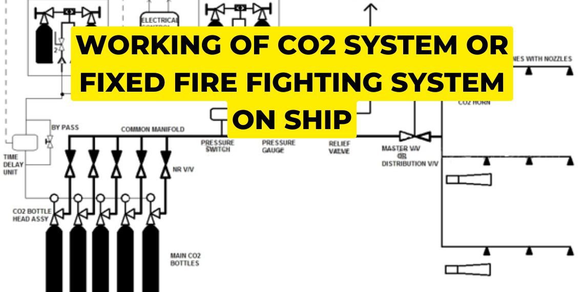
The red-colored pipeline carries CO2, and it has nozzles that inject the CO2 into the engine room when there’s a fire, effectively extinguishing it by depriving it of oxygen. Once the Captain gives the go-ahead signal, it becomes the Chief Engineer’s responsibility to activate the CO2 system in the engine room. Typically, Bulk carriers are equipped with a Fixed CO2 system, while tankers have a Fixed Foam Fire Fighting System installed.
The number of CO2 bottles in the engine room can vary depending on its capacity, but there are approximately 133 of them on average. According to regulations, the CO2 system should flood the engine room within 2 minutes of activation. To meet this requirement, the volume of the engine room is calculated, and the appropriate number of CO2 cylinders is installed.

Onboard CO2 room has three sections:
- CO2 Room
- Fire Control Station
- Engine room
An alarm is raised whenever we open the Mater Control Cabinet, as soon as the CO2 alarm raises, people working I engine room should immediately leave the engine room.
How does Fixed CO2 System work?
CO2 Room
Whenever we open the Master Control Cabinet located in the CO2 room, a relay is activated, triggering an alarm. Inside the cabinet, there are two small CO2 bottles. When we open the valve on these bottles, the CO2 is released. One line connects to the CO2 room, where the released CO2 opens the Main Isolation Valve, allowing the CO2 to enter the room. Another line leads to the Time Delay unit, which contains an orifice. In this case, the Time Delay Unit is an electronic circuit equipped with a timer. Only after the timer expires, the CO2 is released from the bottle connected to the Time Delay unit.

Puncturing of CO2 bottles:

The CO2 from the control panel flows and punctures another bottle in the CO2 room. Initially, the amount of CO2 coming is small, enough to puncture one CO2 bottle but not all of them. However, as soon as one CO2 bottle is punctured, it releases a higher quantity of CO2. This process continues, with each punctured bottle leading to the puncturing of the next one in a rapid manner. The greater the amount of CO2 being released, the faster the bottles get punctured. This vigorous puncturing is necessary because we need to ensure that all the CO2 is released into the engine room within 2 minutes. A single small 7.2kg CO2 bottle cannot puncture all 133 CO2 bottles, but once the pilot bottle is punctured, it sets off a chain reaction, quickly puncturing the rest of the CO2 bottles.
Time Delay unit:

When we open the valve of the Control Station, the CO2 is released and flows into the CO2 room, puncturing the CO2 bottles. However, if the Main Isolation valve fails to open, the pressure in the line will increase. In such a situation, the relief valve will open, causing all the CO2 to be released into the atmosphere instead of reaching the engine room to extinguish the fire. To prevent this, the Time Delay unit is installed to ensure that the Distribution Valve/Main isolation valve opens first before the CO2 bottles release the CO2.
Bypass valve given in the Time Delay unit:
If the Time Delay unit malfunctions, the line gets blocked, or the electronic circuit gets damaged, the bypass valve serves as a backup. The Chief Engineer is responsible for manually opening the valve to release CO2 into the engine room.
Pressure switch and pressure gauge:
If a cylinder bursts in the CO2 room, the released CO2 will flow towards the distribution/Master valve and may also leak into the CO2 room. This leakage can be toxic if anyone enters the CO2 room. In such a situation, the pressure in the Manifold line will increase, triggering the pressure switch that is set at 4 bars. The pressure switch will raise an alarm to indicate the CO2 leakage. We need to manually open the valve located below the pressure switch and check for the presence of CO2.

We fit a pressure gauge in addition to the electrical pressure switch to monitor the pressure in case the switch malfunctions. The pressure gauge allows us to visually observe the pressure and determine if any CO2 cylinder is punctured. This system helps us distinguish between genuine alarms and false alarms caused by equipment malfunctions.
Under normal conditions when CO2 is not in use, the pressure gauge should consistently display zero pressure. However, if there is a leak in the CO2 bottles, the pressure gauge will show an increase in pressure.
Engine room blowers:
The engine room is equipped with blowers that draw in breathable air from the atmosphere and supply it to the engine room. These blowers play a crucial role in maintaining a suitable temperature and ensuring that the main engine generator receives the necessary scavenge air. Without this supply of air, the main engine generator would not be able to operate in a vacuum.
Limit switch:

When we send CO2 into the engine room to extinguish a fire, it is important to ensure that the blowers, which supply oxygen, are not running simultaneously. If both the blowers and the CO2 distribution valve are active, the fire extinguishing process will not be effective.
Therefore, as soon as the Distribution valve opens, a signal will be sent to the Limit Switch, causing it to stop all the engine room blowers. After a certain period of time, the CO2 bottles will rupture, releasing CO2 into the engine room.
Fire Control Station:
From Fire Control Station, one can start fire pumps, emergency stops operate quick closing valves, operate Hypermist System, operate CO2 system and also fire control panel is fitted. The Fire Control Station has another set of valves and cylinder present and the lines from the CO2 room are connected together. So whether you operate the valve of CO2 room or Fire control station it is the same thing.
Note:
If you want to learn more about this topic, we suggest checking out our Combo package with the given link https://merchantnavydecoded.com/courses/c/ . It’s a great way to dive deeper into the subject through video explanations. This package covers all the important details and presents them in an easy-to-understand format. Watching the videos will help you grasp the topic better and make learning more enjoyable. So, we highly recommend giving our Combo package a try to enhance your knowledge on the subject.
Disclaimer :- The opinions expressed in this article belong solely to the author and may not necessarily reflect those of Merchant Navy Decoded. We cannot guarantee the accuracy of the information provided and disclaim any responsibility for it. Data and visuals used are sourced from publicly available information and may not be authenticated by any regulatory body. Reviews and comments appearing on our blogs represent the opinions of individuals and do not necessarily reflect the views of Merchant Navy Decoded. We are not responsible for any loss or damage resulting from reliance on these reviews or comments.
Reproduction, copying, sharing, or use of the article or images in any form is strictly prohibited without prior permission from both the author and Merchant Navy Decoded.

Nicely explained. Except some typo errors which could have been corrected before uploading. Thanks for this informative article.
Hi SK, thank you for the corrective feedback. We’ll look into it and hope to deliver accurate and precise information in the future.
Very well explained