Hi this is Team Merchant Navy Decoded !!!

Please fill the below form with your query and we will get back to you in next 12 hours.

Rest assured your data is safe with us !!!🙂

Ask Your Query

Pressure monitoring and measuring

Pressure monitoring and measuring

There are many pressure sources in an engine room. There is lube oil pressure to the main bearings, fuel pressure at the injectors, jacket water pressure, starting air pressure, boiler steam pressure, hydraulic oil pressure to the steering gear and sea water pressure to the coolers. Pressure is usually one of the first indications an engineer will look at, and if not correct there is likely something going wrong. If the lube oil pump loses pressure then you won’t have much warning before something happens to the bearings.

It is essential to understand how pressure is measured, and how to interpret the signals and alarms. It is also important to understand how to ensure they are correct with calibration.

Pressure basics

Pressure is a force applied to an area. In ships you will see pressure measured in bar, psi, kPa and MPa. Sometimes you will see more than one type of unit used on the same plant. Bar is roughly the pressure of the atmosphere at sea level.

There are a few different types of pressure:-

  • Gauge pressure – This is pressure referenced to the atmosphere. For example if your tyre reads 2 bar it means it is 2 bar above atmospheric pressure. Most pressure instruments on ships will be using gauge pressure.
  • Absolute pressure – This is pressure referenced to a perfect vacuum. Used if the atmospheric pressure is a factor, such as vacuum systems or some boilers or steam systems.
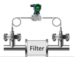
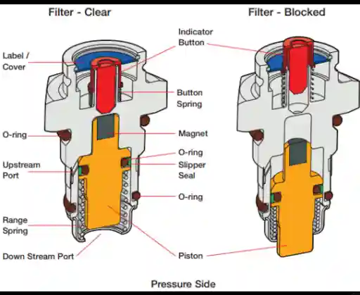
  • Differential pressure – This is the pressure difference between two points. An example would be the pressure drop across a filter. The pressure before minus the pressure after.

If the instrument is not measuring the correct type of pressure it will cause confusion, so always check what it is measuring.

Pressure instruments

There are 3 main types of instruments:-

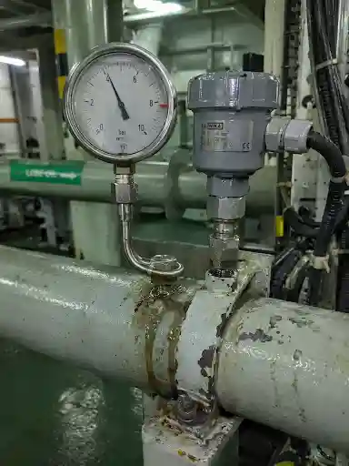
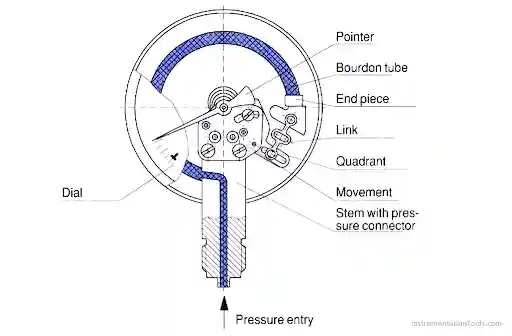
  • Pressure gauges – Local indication. Most are bourdon tube gauges. This is a curved tube that flattens under pressure. The pressure causes the tube to want to return to its original shape causing the needle to move. Simple, tough and no power is required.

Pressure gauges

  • Pressure transmitters – Converts pressure into an electrical signal to be sent to a control or alarm system. Can be viewed in the control room.

Pressure transmitters

  • Pressure switches – Don’t have a range. Just switches the contacts when pressure reaches a set point causing an alarm, trip or start/stop.

Pressure switches

All 3 have a purpose, and generally all 3 will be found on a plant.

Table of Contents

Pressure transmitters

There are 3 key parts to a transmitter:-

  1. Sensor – Pressure is applied to a thin diaphragm causing it to flex very slightly. The sensor will pick up on this. Common types of sensors are strain gauges (piezoresistive – resistance changes as diaphragm flexes) and capacitive (diaphragm moves relative to a fixed plate causing a change in capacitance). Both of these were covered in the transducers post.
  2. Conditioning – The small electrical signal produced will be amplified, temperature compensated and linearised by the transmitter.
  3. Output – The signal is converted into a standard output, most commonly a 4-20mA signal. This means at the minimum end of the range the signal will be 4mA and at the max 20mA. Some also have a digital signal on top of this (such as HART) so that they can be read and configured using a hand held device.

The 4-20mA signal is popular due to it being able to run long distances, not affected by much electrical noise. Also having a 4mA signal rather than 0mA means if there was a break in the wire (0mA) it is easily identified. Most transmitters are 2 wire, meaning the same 2 wires are used to power and send the signal. Typically there will be a 24V DC supply in the loop.

There are two key values to remember:-

  •  Zero – the output at the minimum end of the range. 
  • Span – the difference between the minimum and maximum.

 So if the transmitter was calibrated for 0-10 bar then at 0bar there will be 4mA, at 10bar there will be 20mA. At 5bar there will be 12mA. If zero or span drift then the reading will be incorrect although the transmitter appears to be working. This is where calibration comes in.

Pressure switch

The pressure switch is a simple device. The pressure is applied to a sensor (could be diaphragm, piston or bourdon tube). This pushes against a spring. Once the pressure force overcomes the spring force the sensor will move causing a microswitch to activate inside. The contacts will change.

The spring can be adjusted to change the set point. The tighter the spring the higher the pressure it will trip at.

They also have a differential (deadband). This means that the switch will not reset at the same pressure it tripped at. It will reset at a little lower (or higher depending on the type). For example if you have a low pressure alarm it will trip at 2.0bar falling but will only reset at 2.3bar rising. This means the contacts won’t chatter when the pressure is hovering around the set point. Some have an adjustable differential and some have a fixed differential.

The contacts can be normally open (NO) or normally closed (NC). Safety circuits often use NC contacts so if there was a break in the wire it would cause an alarm. This is the same principle as limit switches.

There are also electronic pressure switches. These use a sensor and electronics to switch an output at a pre-set value. They will generally have a display and it is easy to change the set point. However mechanical switches are still very common due to their simplicity and low cost.

Why is calibration needed?

Instruments will drift over time. Vibrations, temperature, ageing, shocks and overpressure will all cause the readings to change. Even if the transmitter/gauge appears to be working they could be a few % out. This can cause problems with safety/alarm systems.

Calibration is the process of comparing the instrument to a more accurate source to identify how much it is out. On ships this is part of a planned maintenance schedule. It is often a requirement from class on safety critical devices such as boiler/engine protection.

The source should be much more accurate than the instrument. It should also be traceable to a recognised source. The calibration equipment will also be calibrated on a regular basis. Results will be recorded. Often a certificate will be issued.

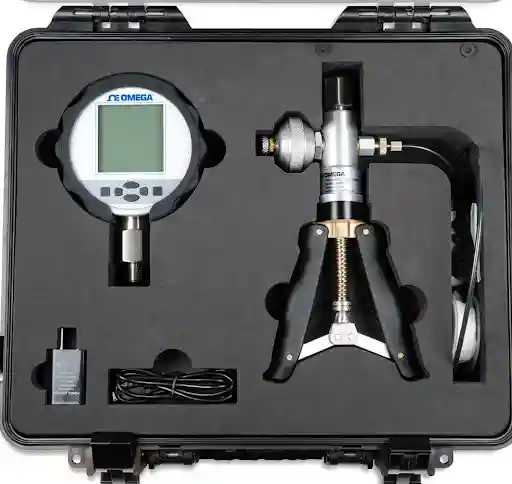
Pressure calibrator

A portable device used to generate and measure pressure.

It will generally have:-

  • A pressure source – Often a hand pump (air/low pressure) or hydraulic hand pump (higher pressure). Sometimes there will also be a fine adjustment knob or built in electric pump.
  • A reference sensor – An accurate pressure sensor. Can be built in or as a module.
  • Display – To show the reference pressure.
  • Electrical measurement – Often a mA reading for transmitter outputs. Some have a loop power supply to power a 2 wire transmitter and read the output. Many can also be used to check switch contacts and automatically record the trip and reset points.

The instrument is connected to the pressure port on the calibrator. Apply pressure using the pump. Compare the true value (from the calibrator) to the value shown.

Calibrating a pressure transmitter

General steps:-

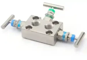
  1. Ensure everything is safe: Inform the control room, put loop/alarm in bypass/inhibit according to the ship’s procedure. Isolate transmitter from process. Depressurise, depending on the installation this can be done on the plant using isolation valves or the transmitter can be removed and tested in the workshop.
  2. Connect up : Connect the calibrator to the pressure port of the transmitter. Connect the mA measurement to the loop. Ensure the hoses and connections are suitable for the pressure being tested.
  3. Check zero: With no pressure applied (transmitter is gauge pressure so vent to atmosphere) the output should be 4mA.
  4. Test multiple points: Apply pressure to approximately 0%, 25%, 50%, 75% and 100%. This should be done going up and then down. Take note of what pressure the calibrator is showing and what mA is being output. Convert the mA to the expected pressure and compare.
  5. Record as-found values: This will show how much the transmitter has drifted.
  6. Adjust if out of range: Firstly adjust the zero then the span. Due to the interaction between the two you will need to check the transmitter again. This can be done using the trim on the transmitter or using a hand held configurator for smart transmitters.
  7. Record as-left values: Ensure they are within tolerance. Check for hysteresis (difference in pressure going up and down) and linearity.
  8. Disconnect: Disconnect testing equipment. Reconnect. Open isolation valves slowly. Take the loop out of the bypass. Confirm with the control room the reading looks correct.

Calibrating a pressure switch

This is to determine what pressure the switch will trip and reset at:-

  1. Isolate and ensure everything is safe. Inhibit associated alarm/trip with correct authorisation. Isolate/remove from the process.
  2. Connect the switch to the calibrator or hand pump with a reference gauge. 
  3. Connect a multi-meter or contact test on the calibrator to the contacts on the switch.
  4. Apply pressure slowly. You don’t want to rush this as it will cause overshoot and an incorrect reading. For a high pressure switch increase the pressure until the contacts change. Note the pressure. This is the trip point.
  5. Go the other way. Decrease pressure slowly until the contacts change. Note the pressure. This is the reset point. The difference in trip and reset is the differential.
  6. Compare to the required set point and tolerance. For a low pressure alarm the pressure will fall to the trip point and then rise to the reset point.
  7. Adjust: If it is not correct adjust the set point screw. This will change the spring tension. Repeat the test. If the switch has an adjustable differential adjust this also.
  8. Repeat a few times to ensure you are getting consistent results. Record as-found and as-left values.
  9. Reconnect switch. De-inhibit alarm/trip. Confirm it is in service. Check it is set to the correct setting in accordance with the ships alarm list.

Safety

Pressure can cause injury if stored. Always isolate and fully depressurise before disconnecting anything. Bleed any trapped pressure through the vent. Ensure the hoses and connections are rated for higher than the pressure being tested. Don’t exceed the maximum pressure of the instrument. Use the correct testing medium. For low pressure air is fine. However for hydraulic testing you need to use a liquid. No-one should use oils or greases near oxygen systems. Don’t stand in line with any fittings being tested. Follow the ship’s permit and isolation procedures. Inform the control room before inhibiting any alarm/trip. Ensure you put it back once finished as forgetting to take it out of bypass can be a real hazard.

Conclusion

A gauge will show pressure, a transmitter will report pressure and a switch will act. Calibration will tell you if they are trustworthy. Understanding how they work, knowing what zero, span, set point and differential mean, testing against a good reference and recording will make pressure readings something you can trust.

Frequently Asked Questions (FAQs)

A transmitter will constantly measure pressure and send a signal (normally 4-20mA) across the range. A switch will only change the contacts when pressure reaches a set point.

Having a 4mA minimum means it is easy to identify if there is a break in the wire (0mA). It also means 2 wire devices will have power.

Zero is the output at the minimum end of the range. Span is the difference between the minimum and maximum. If either drift then the reading will be incorrect.

The difference between the trip and reset pressure. This will stop the contacts from chattering when the pressure is close to the set point.

It will produce a controlled pressure. It will also accurately measure the pressure. Usually it will have a built-in reference sensor. Often it can measure mA and switch contacts so you can compare to a known value.

As-found values are the values the instrument shows without any adjustment. This will show how much it has drifted. As-left values are after adjustment and show it is within tolerance.

Slowly. If you go too quickly you will overshoot and incorrect trip point. Once you have noted the trip point, go the other way slowly.

It depends on the instrument. It will be part of the planned maintenance schedule on the ship. Safety critical devices will be checked more regularly.

Disclaimer :- The opinions expressed in this article belong solely to the author and may not necessarily reflect those of Merchant Navy Decoded. We cannot guarantee the accuracy of the information provided and disclaim any responsibility for it. Data and visuals used are sourced from publicly available information and may not be authenticated by any regulatory body. Reviews and comments appearing on our blogs represent the opinions of individuals and do not necessarily reflect the views of Merchant Navy Decoded. We are not responsible for any loss or damage resulting from reliance on these reviews or comments.

Reproduction, copying, sharing, or use of the article or images in any form is strictly prohibited without prior permission from both the author and Merchant Navy Decoded.

DIWALI SALE

Decoded Discount Alert! up to 50% OFF

DIWALI SALE

Decoded Discount Alert! up to 50% OFF

Use Coupon Code Deep50

Days
Hours
Seconds
0
Would love your thoughts, please comment.x
()
x