Hi this is Team Merchant Navy Decoded !!!

Please fill the below form with your query and we will get back to you in next 12 hours.

Rest assured your data is safe with us !!!🙂

Ask Your Query

Mooring and Windlass Hydraulic Circuit

Mooring and Windlass

Two of the heaviest tasks on a ship are dropping and weighing the anchor.  Getting rid of the anchor by letting go, and raising it again, or tying the ship to the quay by using ropes that can hold large amounts of weight. This is all done by tough, simple looking machinery that is actually very sophisticated. This post will explain what the mooring winch and windlass are, how the hydraulic circuit works, the speed and load control, and why a counterbalance valve is important.

Mooring & Windlass

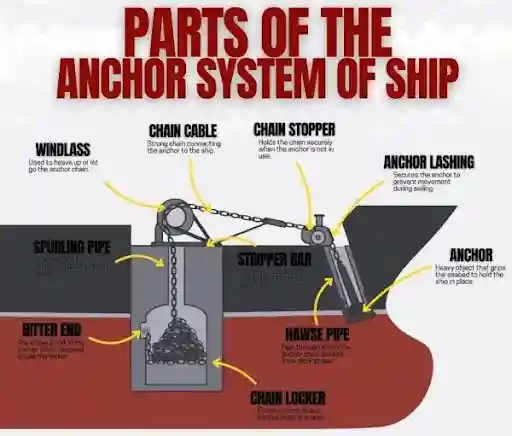
Parts of the anchor system of ship
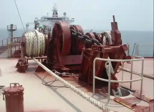
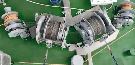
  • A windlass is used to raise/lower the anchor. It contains a cable lifter (gypsy wheel) which grips the anchor chain with pockets to hold onto the links. It is driven by a hydraulic motor with a gear box.
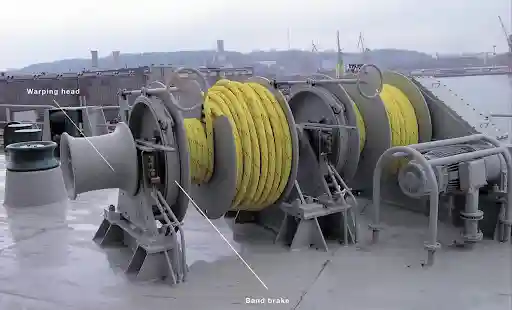
  • A mooring winch is used to raise/lower the mooring ropes keeping the ship tied to the quay and/or buoy. A mooring winch contains a drum for the rope and a warping head/warping drum. It is used to raise the ship to the berth and hold it in place against wind, currents and tides.

On many vessels this can be combined with a Windlass/Mooring winch. It will contain one or two gypsies and mooring drums on a single frame and will take feed from a common hydraulic power unit.

Typically a windlass/mooring winch will consist of:-

  • Hydraulic motor :  It provides the drive
  • Gearbox : To reduce the speed and increases the torque
  • Gypsy (anchor chain) and/or Mooring Drum/Warping Head
  • Clutches – To engage/disengage the drums so the gypsy can be released to let the anchor drop.
  • Band brakes – To hold the load when the motor is not in motion. Can be engaged manually with a handwheel, or via hydraulic/spring actuated brake cylinders.
  • Chain stopper – Relieves the load from the windlass when it is anchored.
  • Local and/or Remote Control – Hydraulic control valve or electric controls.

Why Hydraulic?

Hydraulic systems work well for this application. The motor can provide a high amount of torque at low speeds. It can stall if required and will not be damaged by using a relief valve. The speed can be easily controlled and the power unit can be located in a dry area with just piping to the deck. Hydraulic deck equipment is also safe to use in dangerous areas as there is no electrical equipment on deck.

Circuit Explanation

Circuit Explanation

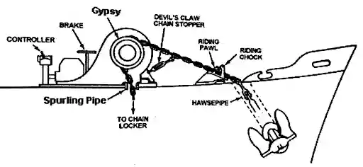
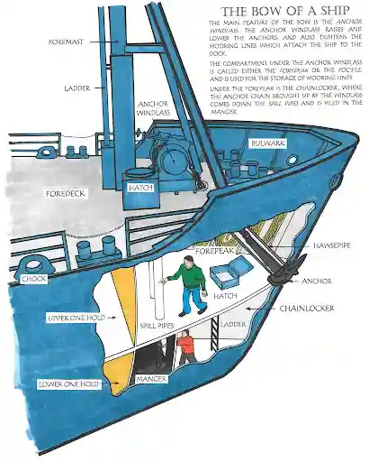
  1. Anchor and hawsepipe: The anchor sits in the hawsepipe, the angled tube through the ship’s side. When it’s stowed, the shank is in the pipe and the flukes are against the hull. The chain runs up through the pipe to the deck.
  2. Riding chock and riding pawl: The chain passes over the riding chock, a support at deck level. The riding pawl is a hinged piece that drops over a chain link, so the chain can’t run out.
  3. Devil’s claw chain stopper: Further along, this hook grips a link and holds the chain. It’s tightened with a screw or turnbuckle. At sea and at anchor, the riding pawl and devil’s claw take the pull from the anchor, so the strain doesn’t go on the windlass.
  4. Gypsy: The chain wraps around the gypsy (cable lifter). Its pockets grip the chain links, so turning the gypsy hauls the chain in or pays it out.
  5. Brake and drive: The brake band holds the gypsy when the drive is stopped. The windlass motor drives the gypsy through a gearbox, and the controller starts, stops and reverses it.
  6. Spurling pipe and chain locker: The chain leaves the gypsy and drops through the spurling pipe into the chain locker below, where it’s stored. The inboard end is secured inside the locker.Many circuits will also have a pressure gauge on the working lines to show the amount of pulling force. Many will also have a flush/boost line to ensure the motor is continually supplied with oil.

Table of Contents

Hydraulic Motor Speed/Load Control

Hydraulic motors behave in a very simple way:-

  • Speed – The higher the flow rate (amount of oil per minute) the faster the motor will spin.
  • Torque – The higher the pressure the more torque. Torque equals pulling force.
  • Power – The amount of power is equal to the torque x speed. 

This means that the motor can be driven at high speeds with low loads or low speeds with high loads depending on the pressure coming from the pump. This is exactly what we want on deck. The windlass will have a high speed to pull in light anchor chains however when the anchor gets stuck in the seabed it will need to slow down and provide a high pulling force. A mooring winch should be able to run at high speeds to take in any slack rope however will slow down once the rope tightens.

The issue with this is if there is a simple fixed pump and throttle valve the motor speed will change depending on load. The higher the load the higher the pressure, more internal leakage/relief valve flow and the motor will run slower. Sometimes not predictably. A speed control is used.

The most common ways are:-

  • Pressure compensated flow control valve – Ensures a constant flow to the motor regardless of pressure. This means the speed remains constant despite changes in load. Any extra flow from the pump will return to tank.
  • Variable displacement pump w/ pressure compensator – The pump will automatically adjust itself to provide the right amount of flow. If there is a heavy load the pressure will increase towards the set pressure and the pump will reduce flow. This means no wasted power. If there is a light load full flow will be provided and the motor will run fast. Saves energy and overheating.
  • Two speed (variable displacement) motor – The motor can be changed between two modes. High displacement mode (high torque, low speed) and Low displacement mode (low torque, high speed). Light loads will run fast and heavy pulling forces will have high torques.
  • Constant power/load sensing – The system will adjust the flow and pressure to ensure the power does not exceed the maximum power of the prime mover. This ensures the electric motor will not overload.

The speed control also allows for precise control at low speeds. For example when paying out the last of the anchor.

The maximum pulling force is determined by the relief valve. It is often set at a stall pressure. This is the highest force the winch can pull with before the pressure relief opens. The brake will have a higher holding force than pulling force so it will hold a load that the motor cannot pull. These values will be given by the manufacturer and will be to the standard of the equipment on the ship.

Counterbalance Valve

Counterbalance valves  are very important on a windlass.

  • Issue: When lowering the anchor the weight of the anchor and chain will try to make the motor spin faster than oil is flowing. This is known as over-running. Without control the anchor will run away, chain will pay out fast and cavitation will occur in the motor as it is spinning faster than oil is being supplied. A throttle valve will not solve this issue as it only restricts the flow.
  • Solution: A counterbalance valve will prevent oil from exiting the motor on the load side. This means the motor can only spin as fast as oil is being supplied to the other side. The pressure on the supply line will act as a pilot signal and will open the valve in proportion. If the load tries to over-run the pilot pressure will reduce and the valve will close slightly reducing the load. This provides smooth controlled lowering.
  • Holding: If the control is in neutral the counterbalance valve will hold the oil in the motor so the load will remain still. The brake will be the main holding device when anchored however the counterbalance valve provides a secondary holding device.
  • Setting: Set slightly higher than the pressure caused by the load. This means no leakage whilst under load. The pilot ratio will be selected to allow smooth opening of the valve. If the pressure is set too low the load will creep. If it is set too high the lowering will be jerky and wasteful.

As the valve holds pressure inside the motor the pipework/hoses between the motor and valve may still be pressurised. Consider them live and depressurise them correctly.

Mooring and Windlass Animation

A good animation will help you understand the circuit. If you are creating or selecting an animation for your blog it should show the following in order with coloured oil flow and labelled moving parts.


  1. Heaving – The directional valve will be moved to one side. Oil will flow from the pump to the motor via the counterbalance valve (check side). The brake will release and the gypsy will rotate pulling in the chain.
  2. Neutral – Valve will be neutral. The pump will unload to the tank. Pressure will reduce and the brake springs will apply. Loads will be held.
  3. Lowering (Veering) – The valve will be moved to the other side. Oil will flow to the other side of the motor. Pilot pressure will cause the valve to open and the anchor can be lowered.
  4. Over-running – The load will try to speed up. Pilot pressure will reduce and the counterbalance valve will close slightly.
  5. Overloading – The pulling force will exceed the set pressure. The relief valve will open and oil will return to the tank. The motor will safely stall.
  6. Mooring – Rope will be on the warping head/drum. The tension will increase as the ship is pulled into the quay.

Common Issues

  • Slow/Weak Operation– Worn pump/motor, low oil level, blocked filter or low relief valve setting.
  • Overheating – Motor stalling, issue with cooler or pump running constantly due to relief valve.
  • Brake not releasing/holding – Stuck brake cylinder, worn brake lining, dirty oil or issue with shuttle valve circuit.
  • Running – Faulty/incorrectly set counterbalance valve.
  • Jerky Operation – Air in oil, sticking valve or incorrectly set counterbalance valve.
  • Leaking – Hoses, pipework and motor shaft seal.
  • Clutch issues – Worn, corroded or not lubricated.
  • Dirty oil – Causes most hydraulic issues.
  • Seizing – Salt, corrosion and lack of greasing.

Best Practice & Safety

  • Always test the brakes, clutches and controls. Check the hydraulic oil level and pressure.
  • Never stand near any mooring lines that are tight. If they become parted they will snap back with lethal force. Everyone should know where the snap back zones are and avoid them.
  • Never stand near any running chain or inside any bights of rope.
  • Do not exceed the rated pulling force. Check ropes and chain for wear.
  • Ensure the brake bands and linings are in good condition. Ensure no oil gets on them.
  • Use the correct hydraulic oil. Filters should be kept clean. Take oil samples as part of planned maintenance.
  • Ensure the counterbalance and relief valve are set as stated. Never adjust without proper procedure and a gauge.
  • Depressurise and isolate any part of the circuit. Chock/Support the load.
  • Lubricate and maintain the gear box, clutches and open gearing.
  • Ensure the deck is dry and clear. Ensure communication is clear between the bridge, forecastle and mooring stations.

Conclusion

A windlass or mooring winch takes a simple hydraulic circuit and provides controlled heavy duty pulling. The pump provides the flow. The relief valve sets the maximum pulling force. The directional valve provides direction. The counterbalance valve holds and controls the load. The speed control balances the speed and load. The brake provides a fail safe hold as it is spring applied. Once you know how to read the circuit from pump to motor you will understand how the oil is flowing in all operations and will be able to identify any faults much quicker.

Frequently Asked Questions (FAQs)

A windlass is used to control the anchor and chain. It uses a gypsy. A mooring winch is used to control the mooring ropes. It uses a drum and warping head. Many vessels will have a combined version.

Has pockets to grip the anchor chain links. Used to pay out/in the chain.

It will apply automatically if there is no hydraulic pressure or if the control is moved to neutral. Provides a fail safe hold.

It sets the maximum pressure. This sets the maximum pulling force. If there is too much load the oil will return to the tank and the motor will stall safely. This protects the gear box and rope.

The speed of the motor depends on the flow. The torque depends on the pressure. If there is a simple throttle valve the pressure will increase with the load causing the speed to reduce. A pressure compensated flow control or variable displacement pump will be used.

It will hold the load when the motor is not moving and also controls over-running loads such as the anchor and chain.

A throttle valve will only restrict the flow. A counterbalance valve will only open in proportion to the pilot pressure.

Area where the mooring line could snap back if it becomes parted while under tension. Everyone should avoid this area when mooring.

Provides high speeds for light loads and high torque for heavy loads by changing the displacement of the motor.

Disclaimer :- The opinions expressed in this article belong solely to the author and may not necessarily reflect those of Merchant Navy Decoded. We cannot guarantee the accuracy of the information provided and disclaim any responsibility for it. Data and visuals used are sourced from publicly available information and may not be authenticated by any regulatory body. Reviews and comments appearing on our blogs represent the opinions of individuals and do not necessarily reflect the views of Merchant Navy Decoded. We are not responsible for any loss or damage resulting from reliance on these reviews or comments.

Reproduction, copying, sharing, or use of the article or images in any form is strictly prohibited without prior permission from both the author and Merchant Navy Decoded.

DIWALI SALE

Decoded Discount Alert! up to 50% OFF

DIWALI SALE

Decoded Discount Alert! up to 50% OFF

Use Coupon Code Deep50

Days
Hours
Seconds
0
Would love your thoughts, please comment.x
()
x