Hi this is Team Merchant Navy Decoded !!!
Please fill the below form with your query and we will get back to you in next 12 hours.
Rest assured your data is safe with us !!!🙂
Ask Your Query| For Beginner | For Professional |
|---|---|
| GME | Engine Side |
| G.P. Rating | Deck Side |
| ETO | G.P. Rating |
| IMUCET & Sponsorship | Combo Offers |
| Free Course | MEO |
| Free Course |
| For Beginner | For Professional |
|---|---|
| GME | Engine Side |
| G.P. Rating | Deck Side |
| ETO | G.P. Rating |
| IMUCET & Sponsorship | Combo Offers |
| Free Course | MEO |
| Free Course |
When on deck there are a lot of things that use hydraulic oil. Hatch covers, deck cranes, mooring winches/windlasses, steerable gear, watertight doors, stern ramps etc. They all use pumps to create pressure, cylinders and motors to do the work and hydraulic valves to direct oil, control how much and at what pressure.
The valves are the brain of the system and knowing what the main types are will help you understand what everything means on a hydraulic circuit diagram.
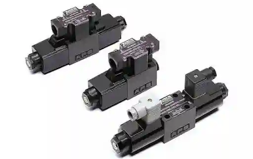
It can be used to control the oil in three different ways. Directional, pressure or flow.
There are also check and counterbalance valves. They are based on the same principles but have specific functions.
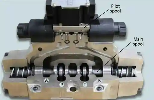
Ports are commonly labelled as follows:-
For example a double acting cylinder like a hatch opener. When the spool is in one position P is directed to A and B to T. This will cause oil to flow to one side of the cylinder and drain from the other, causing extension. When the spool is moved to the other position P will go to B and A to T, causing retraction. In the centre position the ports will be blocked or have a specific connection depending on the valve design.
Want to improve your practical marine engineering knowledge? Explore the Merchant Navy Decoded App, where seafarers can access MND FLIX technical learning resources, MMD exam preparation support, DG Shipping updates, and other useful maritime services.
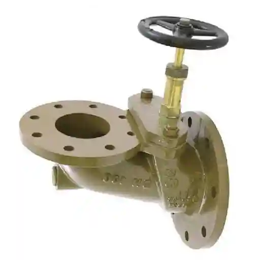
Valves can be identified in a few ways:-
The check valve is the simplest of the valves. It will allow free flow in one direction.Inside there is a ball/poppet that is held onto a seat by a light spring. When oil flows in the correct direction it pushes the poppet off the seat and compresses the spring. This allows free flow. The pressure required to lift the poppet is known as cracking pressure. When oil tries to flow in the wrong direction the pressure and spring force will push the poppet tightly onto the seat.
Uses:
Pilot operated check valves have an extra pilot piston. They operate as a normal check valve in the correct direction, however when a pressure is applied to the pilot line it will push the poppet open. This allows flow in the restricted direction. This is used to hold a load (e.g hatch in the up position) and release on demand. Pilot operated check valves are the basis of many load holding systems.
Flow control valves control how much oil flows to control the speed of the cylinder/motor. The simplest of these are throttle valves (or needle valves). They have an adjustable restriction. The more you open the valve, the more oil will pass through and the faster your actuator will move. Closing the valve will slow down the actuator.
Basic throttle valves have a limitation. The flow through a restriction depends on the pressure drop. If the load changes the speed will change. Pressure compensated flow control valves have an internal compensator to ensure the pressure drop remains constant. This ensures a constant flow regardless of load. This gives a constant speed for things like winches or cargo hatches:-
Often you will want to control the speed in one direction only. A throttle check valve (one-way flow control valve) has a throttle valve and check valve in parallel.
The check valve will be closed meaning the oil must flow through the adjustable throttle valve. This will control the speed. In the opposite direction the check valve will be open and oil will freely flow past the throttle valve. This will give full speed to the actuator.
A typical use would be to have a slow smooth extension but quick retraction. They can be fitted in different orientations to give meter-in or meter-out control on extension or retraction. Check the arrow/symbol on the valve to see which direction the flow is controlled.
It has two components:-
The relief valve will block the oil from leaving the actuator on the load side until opened. This holds the load.
During lowering the load side oil will be trapped by the counterbalance valve. When you want to lower the actuator you will supply oil to the other side. This pressure will act as a pilot signal. The higher the pressure the more the relief valve will open. Oil will now be allowed to flow from the load side. This means the load can only move at the speed the oil is supplied, giving smooth controlled lowering. If the load tries to run away the pilot pressure will reduce, closing the valve slightly and slowing the load down. This is the counterbalance effect.
This will be set to a pressure slightly higher than the load itself. The pilot ratio (e.g 3:1) will tell you how much pilot pressure is required compared to the set pressure.
Counterbalance valves are used on deck cranes, hydraulic hoists, winches, stern ramps and any vertical/overhung load.
These two can be confusing as they both can be used to slow down an actuator.
To sum up, use a throttle valve to set a speed against a constant load. Use a counterbalance valve when the load can push the actuator (e.g lowering a heavy item) and you need to hold and control it.
Many circuits will use both. For example a crane may have a counterbalance valve on the hoist to hold and control the load but also a flow control valve to set a max speed.
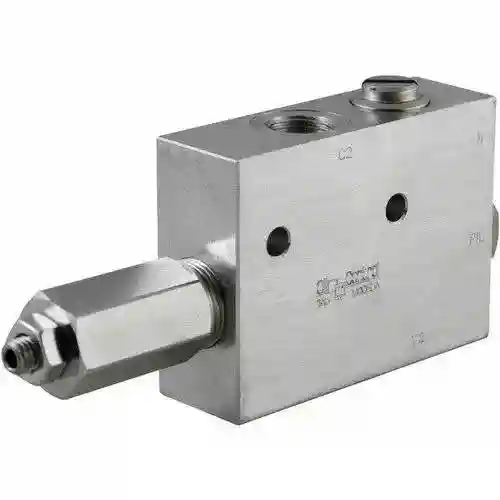
Although hydraulic valves can look like little metal blocks they all have a specific function. Directional valves direct oil, check valves only allow flow in one direction, flow control valves set a speed, throttle check valves only allow flow in one direction and counterbalance valves hold and control a load that wants to run away. Knowing what each valve does and keeping the oil clean will make operating and fault finding on a hydraulic system on deck much more predictable.
Directional control valve, pressure control valve, flow control valve, check valve and counterbalance valve.
P = Pressure supply from pump. T = Return to tank. A & B = Work ports connecting to the actuator.
4 ports and 3 positions.
Closed centre – All ports blocked. Open centre – All ports to tank. Tandem centre – Pump unloads and actuator held. Float centre – Actuator ports to tank.
Spring loaded ball/poppet. Will allow flow when pressure exceeds cracking pressure. Will seal in the opposite direction.
Holds a load by restricting flow in one direction. Can be released on demand by pilot pressure opening the poppet.
An adjustable throttle with a check valve in parallel. Restricts flow in one direction.
A throttle is just a restriction. It can’t hold or control an overrunning load. A counterbalance valve can hold the load and only allow it to lower at the speed oil is supplied.
Ratio between pilot pressure required and pressure set on the valve. E.g 3:1.
Contaminated oil. Can cause sticking spools, worn seats and orifices.
Disclaimer :- The opinions expressed in this article belong solely to the author and may not necessarily reflect those of Merchant Navy Decoded. We cannot guarantee the accuracy of the information provided and disclaim any responsibility for it. Data and visuals used are sourced from publicly available information and may not be authenticated by any regulatory body. Reviews and comments appearing on our blogs represent the opinions of individuals and do not necessarily reflect the views of Merchant Navy Decoded. We are not responsible for any loss or damage resulting from reliance on these reviews or comments.
Reproduction, copying, sharing, or use of the article or images in any form is strictly prohibited without prior permission from both the author and Merchant Navy Decoded.
Decoded Discount Alert! up to 50% OFF
Use Coupon Code Deep50