Hi this is Team Merchant Navy Decoded !!!

Please fill the below form with your query and we will get back to you in next 12 hours.

Rest assured your data is safe with us !!!🙂

Ask Your Query

Hydraulic Pumps and their uses on ship

Hydraulic Pumps

All hydraulic systems start with a pump. It takes oil from a tank and pumps it into the system. This oil is then used in various places including hatch covers, winches, lifting cargo, moving the rudder and working the watertight doors. The pump is what provides the oil for the valves, cylinders and motors to work.

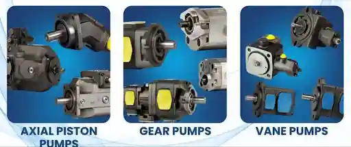
There are three main types of hydraulic pump onboard ships. They are all similar in that they provide oil, but differ in how they operate, the pressure they can cope with and what they are used for. We’ll look at each one.

Want to understand how hydraulic pumps and systems work onboard ships?

Explore our Ship Hydraulic System Course by Merchant Navy Decoded. Learn about hydraulic components, working principles, and their applications in shipboard machinery through practical explanations.

What is a Hydraulic Pump?

A hydraulic pump is a device that converts mechanical energy in the form of an electric motor or engine, into hydraulic energy. The pump does not create pressure. It creates flow. Pressure will develop when there is resistance in the line, for example if there is a load on the cylinder or a valve closed. If the oil cannot easily flow it will build up pressure until something moves or a relief valve is opened.

Nearly all hydraulic pumps are Positive Displacement. This means that for every revolution of the pump it will push a set amount of oil out, regardless of the outlet pressure. This is very different to a centrifugal pump as it will just create a flow that decreases with pressure. Because it is a positive displacement pump a relief valve must be fitted to every hydraulic circuit.

Key Terms:-

  • Displacement – The amount of oil that is pumped per revolution (cc/rev).
  • Flow – This is calculated by multiplying the displacement by the speed. If a pump had a displacement of 50cc/rev and a speed of 1500rpm it would give an approximate flow of 75L/min (excluding leakage).
  • Fixed Displacement – For every revolution the pump will deliver the same amount of oil.
  •  Variable Displacement – The displacement can be altered whilst the pump is running. This allows flow to vary without changing the speed. This saves energy as it only delivers what the system requires.

Gear Pumps

These are the simplest most common pumps. They are durable and can cope with dirty oil.

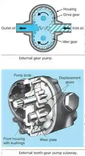
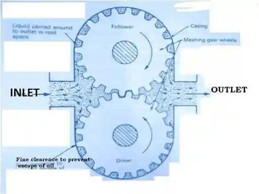
  1. External Gear Pump – Two interlocking gears are housed in a tight casing. One of the gears is driven by the motor which drives the other gear. Oil is drawn into the pump via the inlet. As the gears rotate the inlet side has teeth separating creating space for oil to be drawn in. The oil is forced around the outside of the gears and trapped between the teeth and casing. Once the oil reaches the outlet side the teeth interlock forcing the oil out of the outlet port. The interlocking of the teeth also seals the oil so it cannot flow back to the inlet.

External Gear Pump

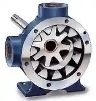
2. Internal Gear Pumps – A small gear is placed inside a large ring gear. There is a crescent divider. The principle is the same but they are generally quieter and smoother.

Internal Gear Pumps

Internal Gear Pump

Advantages:-

  • Simple, durable and cheap.
  • Few moving parts are so reliable.
  • Can cope with dirty oil better than vane and piston.
  • Small size for the amount of flow.

Disadvantages:-

  • Generally fixed displacement.
  • Lower efficiency and are prone to wear as the gaps will open up over time. The oil will leak from the tips and sides of the gears.
  • Loud.
  • Generally cannot cope with high pressures. They are suited to low/medium pressure.

Used for auxiliary functions like lubrication and transfer pumps, pilot/charge pumps to feed larger systems, and small power packs. They are also used as the oil supply for many gearboxes and engine lube systems.

Table of Contents

Vane Pumps

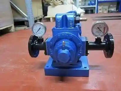
Vane Pump

These are in the middle. They are quieter and smoother than gear pumps. They are cheaper and simpler than most piston pumps.

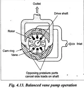
  1. Vane Pump – A rotor with slots is placed inside a cam ring. Sliding vanes fit inside the slots. As the rotor spins the vanes are forced outwards against the inside of the ring. This could be by centrifugal force, spring force or hydraulic pressure. This ensures that the tip of the vane is always in contact with the ring. The rotor is offset so there will be more space between the rotor and the ring (pumping chamber).At the inlet side of the pump there is more space between two vanes so oil is drawn in. The vanes are then moved around by the rotor and at the outlet side the space between the vanes gets smaller forcing the oil out under pressure.
  2. Unbalanced Vane Pumps – These have one inlet and outlet. There will be pressure on one side of the rotor causing loading on the bearings.
  3.  Balanced Vane Pumps – These have an oval cam ring. There will be two inlets and outlets on either side. This means the pressure forces on the rotor cancel out. This reduces the loading on the bearings meaning higher pressure can be achieved and it will last longer. Balanced pumps are fixed displacement as the shape of the ring cannot change.

4. Variable Displacement – A round ring can be moved relative to the rotor. The further it is offset the higher the displacement. Moving it closer to the centre will reduce the displacement. There will be a pressure compensator to automatically adjust the displacement to only supply the required amount of flow.

Advantages:-

  • Quiet with smooth flow and minimal pulsation.
  • Good efficiency over a range of speeds.
  • Available in variable displacement.
  • Easy to service in cartridge form.

Disadvantages:-

  • Sensitive to oil cleanliness. The vanes can become stuck or cause scoring on the ring due to dirt.
  • Wear on the vanes and ring.
  • Generally cannot cope with high pressures. They are suited to medium pressure.
  • Require good quality oil with the correct viscosity.
  • Used for medium pressure hydraulic circuits such as deck machinery power packs, some steering gear systems and cargo handling.

Piston Pumps

These are the high performance options. They can cope with the highest pressures, they are the most efficient and are the standard for high performance systems. However they are the most complex and expensive and require the cleanest oil.

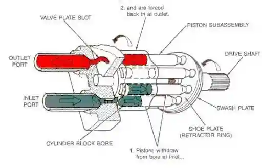
All piston pumps work by having pistons that move in and out of the bores in the cylinder block. As the piston extends it draws in oil. When it retracts it pushes the oil out. There are two main types.

1. Axial Piston Pumps – The pistons are arranged in a circle parallel to the drive shaft. As the cylinder block rotates the pistons are forced in and out of the bores by an angled surface. There are two common ways of achieving this:-

  • Swash Plate – The cylinder block rotates and the end of the pistons (with sliding shoes) slide against an inclined plate known as a swash plate. This incline causes the pistons to extend and retract once per revolution. The greater the angle the greater the stroke and the more oil will be delivered per revolution. Altering the angle alters the displacement giving a variable displacement pump. If the plate is set to 0 degrees there will be no stroke and no flow. Some pumps will have the swash plate able to be angled both ways meaning the flow can be reversed without changing the direction of the motor. This makes them suitable for closed circuit drives.
  • Bent Axis – The drive shaft and cylinder block are at an angle. This causes the pistons to be forced in and out. Bent axis pumps are very efficient and strong.This type is used in the HPS units on the engines as it has a pilot valve and feedback. See HPS construction post.

2. Radial Piston Pumps – The pistons are arranged radially around a central rotor. The pistons are moved in and out by an eccentric cam/ring. These can deliver very high pressures with less flow. They are used in specialised high pressure situations.

Advantages:-

  • Can cope with the highest pressure.
  • High efficiency.
  • Easy to achieve variable displacement with good control.
  • Long life with clean oil.

Disadvantages:-

  • Complex and expensive.
  • Very sensitive to contamination and oil quality.
  • Must be carefully installed, primed and started up. They will quickly suffer if they run dry.
  • Usually requires specialist skills to repair.
  • Used for steering gear, these are commonly variable displacement axial. They are also used for deck cranes, winches and windlasses, hatch cover systems, stern thrusters, engine hydraulic supplies (HPS), and other high pressure/variable flow systems.

Selecting A Pump

This is a balance between pressure, flow, efficiency, noise, cost and oil quality.

Gear pumps are great for simple, cheap and durable pumping with moderate pressures and possibly not the cleanest oil. Vane pumps are good for medium pressure systems that need to be quiet. Piston pumps are chosen when high pressure, high efficiency and variable flow are required along with very clean oil.

Generally you will find gear pumps for low pressures, vane pumps for medium pressures and piston pumps for high pressures. This depends on the design and what the manufacturer states.

Drive

Most hydraulic pumps on board will be driven by an electric motor. Often directly connected. Some may be driven from the engine using a gearbox or power take off. For example the HPS pumps are engine driven. In a power pack there will be a pump, motor, reservoir, filter, relief valve and cooler.

Common Issues
  • Cavitation – If there is not enough oil coming into the pump (strainer blocked, low level in tank, thick oil due to cold or restricted suction line) air bubbles will form and collapse in the pump. This will cause noise and damage to internal components.
  • Aeration – Air is drawn into the suction side due to a leaking joint or low oil levels. This causes foaming and a noisy, spongy pump.
  • Contamination – The main killer of pumps. Dirt and water in the oil will cause wear and blockages in small passages.
  • Wear – Over time the internal clearances will increase causing more internal leakage. This will reduce flow, cause the pump to run hotter and produce less pressure.
  • Overheating – Oil will thin causing more internal leakage.
  • Incorrect rotation, running dry – If the pump is started with no oil or in the wrong direction it can be destroyed in seconds.
  • Leakage from shaft seal.
  • Incorrect setting of relief valve.

Best Practice

  • Ensure oil is clean. Filters and breathers should be changed regularly. Regular checks on oil quality and water content.
  • Ensure oil level is correct and there is no blockage in the suction strainer.
  • Ensure the pump is primed and rotating in the correct direction.
  • Listen for changes in noise. Monitor temperature and pressure. A whining pump often indicates cavitation or aeration.
  • Do not tamper with relief/compensator settings. Follow proper procedures and use a gauge.
  • Stop the pump and de-pressurise before opening any hydraulic circuits. Ensure there is no load being held by the oil.
  • Use the correct grade of oil. Viscosity is important for all pumps.
  • Keep a log of pressure, flow and temperature readings so you can see when performance starts to drop.

Conclusion

All three pumps trap oil and force it out but they all do it differently. Gear pumps are simple, durable and can cope with harsh conditions. Vane pumps are quiet and smooth. They are in the middle for pressure. Piston pumps (swash plate or bent axis) can cope with the highest pressures and offer the best control. As long as they are supplied with clean oil. Choose the correct pump for the application, ensure the suction side is in good condition and the oil is clean and your pump will last for years with little maintenance.

Frequently Asked Questions (FAQs)

Its main function is to supply clean, properly conditioned fuel to the auxiliary diesel engine to ensure reliable combustion and electrical power generation.

A purifier removes water and solid impurities from fuel using a centrifuge.

A heater reduces viscosity of heavy fuel oil so that it can circulate and be injected under suitable conditions. The fuel and engine specifications will dictate whether it is needed and the degree of heating.

It provides the right quantity of fuel at injection pressure levels to the injector at the right time.

A blocked filter causes fuel flow restriction which results in low supply pressure and engine power loss, instability or shutdown.

Excess fuel is returned to maintain stable supply conditions and to allow the system to circulate more fuel than the engine consumes.

Disclaimer :- The opinions expressed in this article belong solely to the author and may not necessarily reflect those of Merchant Navy Decoded. We cannot guarantee the accuracy of the information provided and disclaim any responsibility for it. Data and visuals used are sourced from publicly available information and may not be authenticated by any regulatory body. Reviews and comments appearing on our blogs represent the opinions of individuals and do not necessarily reflect the views of Merchant Navy Decoded. We are not responsible for any loss or damage resulting from reliance on these reviews or comments.

Reproduction, copying, sharing, or use of the article or images in any form is strictly prohibited without prior permission from both the author and Merchant Navy Decoded.

DIWALI SALE

Decoded Discount Alert! up to 50% OFF

DIWALI SALE

Decoded Discount Alert! up to 50% OFF

Use Coupon Code Deep50

Days
Hours
Seconds
0
Would love your thoughts, please comment.x
()
x