Hi this is Team Merchant Navy Decoded !!!
Please fill the below form with your query and we will get back to you in next 12 hours.
Rest assured your data is safe with us !!!🙂
Ask Your Query| For Beginner | For Professional |
|---|---|
| GME | Engine Side |
| G.P. Rating | Deck Side |
| ETO | G.P. Rating |
| IMUCET & Sponsorship | Combo Offers |
| Free Course | MEO |
| Free Course |
| For Beginner | For Professional |
|---|---|
| GME | Engine Side |
| G.P. Rating | Deck Side |
| ETO | G.P. Rating |
| IMUCET & Sponsorship | Combo Offers |
| Free Course | MEO |
| Free Course |
Traditional camshaft engines have injection and valve timings built into the camshaft. The camshafts are machined and timed to the crankshaft. However, on an electronically controlled engine like the RT-flex, this is done via the control system. The control system will decide the timing, quantity and when to open the exhaust valves for each cycle and cylinder.
This makes the control system the ‘brain’ of the engine. The engine will also have a safety system to protect the engine and an alarm & monitoring system to inform engineers. This post will look at these systems.
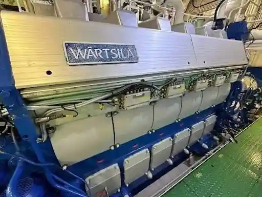
The RT-flex is a 2 stroke low speed engine with no camshaft. Instead of having mechanical fuel pumps and camshafts for each cylinder, it has a common rail fuel system with 2 rails.
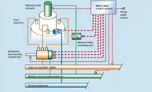
The supply unit is driven by the crankshaft using a gear train. This has the high pressure fuel pumps and servo oil pumps to create the pressure in the rails. The principle is similar to the HPS. The pressure is then distributed to the cylinders via the rail unit which contains the electronically controlled valves to open and close injection and move the exhaust valves.
For each cylinder the control system will have to tell the engine to open and close the injection valve and open/close the exhaust valve at the correct order and crankshaft angle. This is done by the engine control system.
As the timing is done electronically, it can be varied to provide:-
Want to improve your practical marine engineering knowledge? Explore the Merchant Navy Decoded App, where seafarers can access MND FLIX technical learning resources, MMD exam preparation support, DG Shipping updates, and other useful maritime services.
The control system on the Wärtsilä RT-flex engine is known as the WECS. This will vary slightly depending on what generation the engine is but will generally follow the same pattern.
The WECS consists of a number of electronic modules, usually fitted to the engine itself. There will be a module for each cylinder to control injection and exhaust valve timings. There will also be one or more modules to control the overall engine.
The WECS will control:-
In order to perform these functions the control system will require sensors. The most important being the crankshaft angle sensor (angle encoder) although there will also be speed, rail pressure, temperature and valve feedback sensors. If it cannot get the crankshaft angle it will not be able to time anything.
The WECS does not receive direct commands from the bridge. The bridge telegraph and control lever will send signals to the remote control system which will process the manoeuvring logic (See manoeuvring system section of angle encoder post), check interlocks, and send a speed set point, start/stop and direction command to the WECS. This will then be carried out.
Due to the importance of the control system, it is designed so that a single fault will not cause the engine to stop. This is usually done by having duplicate modules for important functions, 2 communication networks, 2 power supplies and 2 crankshaft angle sensors. If a part fails, the other will take over and cause an alarm. This is the most important part of the design so a fault should cause an alarm rather than stopping the engine.
The control system will have reliable power supplies. Usually there will be a back up from batteries/UPS.
There are 3 places you can control the engine from, the bridge, engine control room and local control panel on the engine. There will be a change over to ensure only one station is controlling at any one time. The local control can always take over as it is the last resort if the remote systems fail. All of the control stations will go through the remote control system. The local control will also have emergency controls.
The safety system will protect the engine. Whilst the control system aims to run the engine, the safety system looks out for any potentially damaging conditions.
Independent: The safety system is deliberately kept separate from the control and alarm systems. This means it has its own sensors, logic and power. This means if there is a fault with the control system, the engine can still be protected. The safety systems are not affected by any faults.
Stop & Slow.
The 2 main ways the safety system can protect the engine are:-
Typical reasons for stopping would be very low lube oil pressure, engine overspeed, oil mist detector alarm in the crankcase and issues with the thrust bearing. Typical reasons for slowing would be high exhaust gas temp, high jacket cooling water temp, high scavenge air temp and low cooling water pressure. This will depend on the engine manufacturer and class society.
Emergency stop: There is also an emergency stop manually available at the control stations. This can be used by the engineer or bridge to stop the engine.
Overspeed: There is an overspeed trip to stop the engine if it goes over a set speed.
Override: Some of the stop and slow functions can be overridden from the bridge or ECR in emergencies. For example, if the ship needs to keep moving to avoid running aground or colliding. The operator will knowingly take the risk of damaging the engine. Not all safety functions can be overridden though. The ones that can’t, such as overspeed and crankcase oil mist stop on many installations will still be active. Rules and settings will vary per ship and class.
Restart: The engine will not be able to be restarted after a stop until the cause has been identified and the system reset. This is deliberately done so that if you restart the engine without knowing why it stopped you could cause serious damage.
Testing: The safety functions will need to be tested regularly as per the planned maintenance system and class. This means the engineers know they will work when they need to. This includes testing the stop/slow functions, overspeed trip and emergency stop. Never disable or override a safety function to keep the engine running.
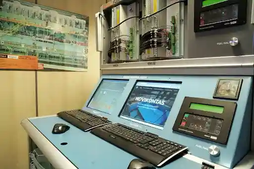
The monitoring & alarm system (AMS) is part of the control system to inform the engineers. It will monitor hundreds of sensors throughout the engine and machinery. It will display, log and alarm if anything is out of the normal range.
Monitors :-
Each will have set limits. If they go above or below the set limits an alarm will show on the AMS screen. This will have an audible and visual alarm. The engineer will acknowledge the alarm and this will silence the alarm, however the alarm will still be displayed until the fault has been resolved. Some systems will have multiple alarm levels, for example pre-alarm, alarm, slow or stop.
Many alarms will have a small delay. This is to stop false alarms from temporary spikes. Some will also be inhibited whilst starting or manoeuvring as the pressures and temps are not at normal levels.
The alarms will be sent from the engine room to the bridge, cabins and public rooms via the engineers call system. This means the duty engineer will be informed of any faults. If the alarm is not acknowledged within a set time, the call will escalate. (See engineers call alarm post).
The system will also monitor the sensors. If there is a break in the wire e.g. 4-20mA drops to 0, it will show a sensor fault.
The AMS will log any alarms, along with the time they occurred and were resolved. It will also show trends for important readings. This can help identify faults.
If the machinery is unattended, there will be a watchkeeping alarm to ensure the engineer is still responsive. If they are not, an alarm will be raised.
The AMS will alert you whereas the safety system will take action. The AMS will alert you that there is an issue. Whereas the safety system will slow or stop the engine. They will have separate sensors and logic so the monitoring system will not disable the protection.
The control, alarm & monitoring and safety systems can be thought of as 3 layers :-
Each has their own sensors and logic so a fault in one will not disable the others. A typical example would be if the lube oil pressure starts to drop, the AMS will raise an alarm for low pressure. The duty engineer will be called and start to investigate. If the pressure continues to drop to the stop level, the safety system will stop the engine to prevent damage to the bearings.
The RT-flex engine has no cams and instead uses electronics. This means the control system has a lot of responsibility. The WECS will decide when to inject and open/close the exhaust valves using the crankshaft angle and rail pressures. The alarm & monitoring system will keep the engineers informed. The safety system is independent and will slow/stop the engine if a dangerous situation occurs. Knowing what each layer does, they are separate and what each alarm, slow and stop means will help you respond to the engines alarms in the correct order.
A Wärtsilä low speed 2 stroke engine with no camshaft. It uses electronically controlled fuel injection and exhaust valves using common rail fuel and servo oil.
It is the engine control system. It controls fuel injection, exhaust valve timing, starting air valves, cylinder lubrication, rail pressures and speed governing.
It uses the crankshaft angle to time all injections and valve openings. Without it it would not know where each piston was.
The alarm & monitoring system will alert the engineers. Whereas the safety system will automatically slow/stop the engine. They are separate and have their own sensors and logic.
A slow will reduce the load and speed of the engine so it can still run. A stop will stop the engine by cutting the fuel.
Some can be overridden in emergencies such as to avoid running aground. However not all can be. Overspeed for example cannot be overridden. Details will vary per ship and class.
The cause must be identified and the system reset. If you restart without knowing why it stopped it could cause serious damage.
So a single fault will not stop the engine. If one module, network, power or sensor fails an alarm will be raised and the other will take over.
To avoid false alarms from temporary spikes. During starting/manoeuvring pressures/temps will not be at normal levels.
They are sent to the bridge, cabins and public rooms via the extension alarm and engineers call system. If no one acknowledges it will escalate.
Disclaimer :- The opinions expressed in this article belong solely to the author and may not necessarily reflect those of Merchant Navy Decoded. We cannot guarantee the accuracy of the information provided and disclaim any responsibility for it. Data and visuals used are sourced from publicly available information and may not be authenticated by any regulatory body. Reviews and comments appearing on our blogs represent the opinions of individuals and do not necessarily reflect the views of Merchant Navy Decoded. We are not responsible for any loss or damage resulting from reliance on these reviews or comments.
Reproduction, copying, sharing, or use of the article or images in any form is strictly prohibited without prior permission from both the author and Merchant Navy Decoded.
Decoded Discount Alert! up to 50% OFF
Use Coupon Code Deep50