Hi this is Team Merchant Navy Decoded !!!

Please fill the below form with your query and we will get back to you in next 12 hours.

Rest assured your data is safe with us !!!🙂

Ask Your Query

RT-flex ICU and VCU Function

RT-flex ICU and VCU

On a cam-operated engine the camshaft has cams that will push the fuel pump and exhaust valve at the correct time due to the profile of the cam. However, on an RT-flex engine there are no cams. Instead there are two small units located on each rail unit of the cylinder. These units are instructed by the electronic control system and are called the ICU (injection control unit) and the VCU (valve control unit).

The ICU and VCU can be thought of as the muscle of the engine with the control system acting as the brain. This post is looking at what these units do, how the control functions work and what happens during a normal cycle.

Location

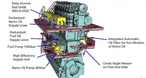
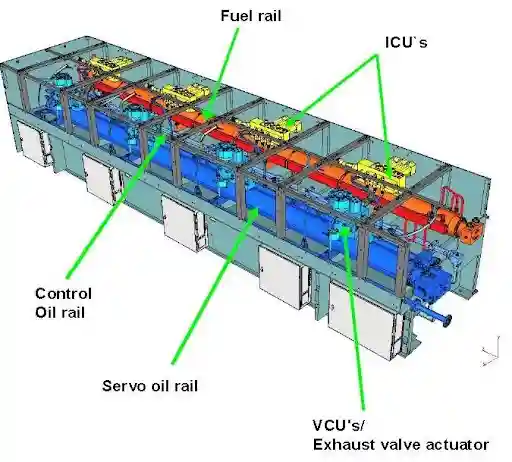
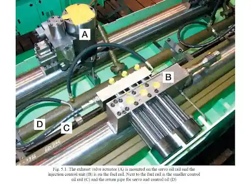
As we know from  the RT-flex engine uses a common rail system. Within this there are two rails running along the engine.

 One contains high pressure fuel and is called the fuel rail. The other contains high pressure hydraulic oil and is called the servo oil rail. These connect to the rail unit on each cylinder.

This rail unit contains:-

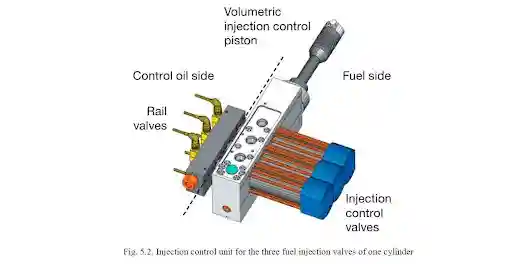
  • An ICU that will take fuel from the fuel rail and control how much and when the fuel is sent to the injectors.
  • A VCU that will take servo oil from the servo oil rail and control the hydraulic actuation of the exhaust valve.

These units do not make any decisions. They are simply instructed by the control module for each cylinder. These parts will vary depending on the generation of engine so the manual should be referenced for specifics.

Learn More with the Merchant Navy Decoded App

Want to improve your practical marine engineering knowledge? Explore the Merchant Navy Decoded App, where seafarers can access MND FLIX technical learning resources, MMD exam preparation support, DG Shipping updates, and other useful maritime services.

Explore the Merchant Navy Decoded App

Fuel and Valve Control

Fuel and Valve Control

Both of these functions are at different points within the cycle and are highly related as they depend on piston position.

Within a 2 stroke engine the cycle will be:-

The piston moves up to shut the scavenge ports and compress the air. Fuel is injected near the top of the stroke and burning occurs. The piston is forced down. Midway through the stroke the exhaust valve opens allowing burnt gas to escape. Scavenge ports open allowing fresh air in. The rest of the exhaust gas is forced out. As the piston begins to move up the scavenge ports close and the exhaust valve closes. Compression begins.

The control system needs to control:-

  • Injection start and end – This determines when the combustion will occur and how much fuel is injected.
  • Exhaust valve opening – This determines how well the cylinder will empty.
  • Exhaust valve closing – This affects how much air is trapped and so the compression pressure.

On a camshaft engine these are all fixed. However, on an RT-flex engine the control system can change these to match the load, fuel and conditions. This is the main benefit of this system and is achieved using the ICU and the VCU.

Table of Contents

Common Control Function

There are two parts to the control functions. The first part is the common control function.

This handles:-

  • Speed control – Compares the desired speed from the remote control system to the actual speed and calculates how much fuel is required.
  • Start/stop – This includes start air valves.
  • Rail pressure – Controls the pumps on the supply unit to ensure the fuel and servo oil rails are at the correct pressure for the current load.
  • Fuel quantity and timing – Determines the basic fuel quantity, injection and exhaust valve timing required for the current speed and load. Sends this information to each cylinder.
  • Balancing – Adjusts individual cylinders to ensure even loading.
  • Communication – With the remote control system, safety system and alarm and monitoring system.
  • Protection – Cuts cylinders out if a fault occurs. Reduces load and handles shutdown requests.

This can be thought of as the planning part. It determines what the engine should be doing overall and sends instructions to individual cylinders.

Crank Angle Detection Function

All of this requires knowledge of where each piston is. The crank angle detection function provides this.

It takes the signal from the absolute angle encoder (see angle encoder post) usually from 2 redundant systems. It determines the crank angle at any point in time. By using the firing order and knowing the TDC position of each cylinder it can tell each cylinder module exactly where its piston is.

This also gives:-

  • Engine speed – By determining how fast the angle is changing.
  • Rotation direction – Important for ahead/astern.
  • A common time base – All modules are using the same crank angle.

It also compares the 2 encoders. If they don’t match or one stops giving a signal then the system will raise an alarm. If possible it will continue using the good encoder. If no crank angle is available then the engine control won’t be able to control the injection and valve timings and the engine may stop or not start.

Accuracy will depend upon the offset between the encoder zero and actual crankshaft position. This is set during commissioning and should be checked after any work is carried 

out on the encoder or drive. If this is incorrect all timings will be incorrect.

Injection Control Function

This takes the fuel demand and injects it. This is for each cylinder and takes the crank angle and settings from the common control function.

It will:

  • Calculate requirements – Knows how much fuel should be injected into this cylinder and when based on the information from the common control function.
  • Send command to ICU – The cylinder module will open the electronically controlled valves within the ICU at the correct crank angle. Fuel will flow from the high pressure rail.
  • Control – The ICU will close at the correct time ensuring the correct amount of fuel is injected.
  • Monitor – Checks that the unit has done what it was asked by monitoring the feedback signals. If not it will raise an alarm.

Since the rail is high pressure the injection pressure will not be affected by the engine speed as it would be with a camshaft driven pump. This means that at low speeds the engine can inject at full pressure. This helps ensure clean combustion at low loads.

  • Injector selection – There are typically multiple injectors on an RT-flex cylinder. The ICU can control each individually. At low loads only some injectors will be used resulting in a good fuel spray and less smoke. As the load increases more injectors will be used. This will depend on the type of engine.
  • Protection – The injection system will have protection functions. These will determine if the unit is unresponsive, leaking or having issues with the rail pressure. The cylinder will be cut out if required. This will vary depending on the design.
Injection Control Function

Exhaust Valve Opening Control

This does the same as the injection control function but for the exhaust valve. This uses the VCU.

The exhaust valve is opened using servo oil and closed using an air spring. The VCU controls the servo oil to the actuator. This will:

  • Open – The cylinder module will instruct the VCU to send pressure from the servo oil to the actuator at the correct crank angle. This will push the valve open against the air spring.
  • Stay open – The valve will stay open during the exhaust and scavenge stage.
  • Close – The VCU will release the oil at the correct crank angle. The air spring will push the valve closed.

A position sensor is fitted to the actuator. This will tell the control system the actual position of the valve. The actual movement will be compared to the command. If the valve doesn’t open/close at the correct time or is slow then an alarm will be raised.

The benefit of this is that the control system can change the opening/closing times based on load and conditions. The valve can be opened/closed earlier or later to change the compression pressure and air trapped. This will affect efficiency and combustion. On a camshaft engine this would require a different cam.

The air spring is also a safety feature. If the servo oil pressure is lost the air spring will push 

the valve closed.

Cycle

Looking at one cylinder will show how everything works.

  1. The crank angle detection function will tell us the piston is moving up during compression.
  2.  The common control function will have determined how much fuel and when based on the current load.
  3.  The rail pressures will be maintained at the correct pressure. 
  4. As the piston reaches the top of the stroke the injection control function will open the ICU at the correct crank angle. Fuel will be injected and burnt pushing the piston down. 
  5. The exhaust valve opening control function will tell the VCU to open the valve at the correct crank angle. Burnt gases will exit and scavenge air will enter. As the piston moves back up the VCU will release the oil and the air spring will push the valve closed. This will repeat for each cylinder based on the firing order. The common control function will continue to alter the settings based on load.
Cycle

Feedback, Sensors & Communication

There will be feedback from these units. Typical feedback will include rail pressures, exhaust valve position, crank angle, engine speed and status signals. Each cylinder module will communicate with each other and the common control function using duplicate networks. This means if one network fails the engine will still operate. If any modules or units fail then an alarm will be raised and the engine will try to continue with the cylinder cut out.

Common Issues

  • Issues with servo oil/fuel rail pressure due to an issue with the supply unit, leak or faulty pressure sensor.
  • Dirty servo oil causing the quick response valves to be slow/stuck.
  • ICU/VCU unresponsive due to faulty valve, coil or connection.
  • Exhaust valve position deviation due to sticking actuator, air spring or sensor.
  • Crank angle sensor faulty/disagreement affecting all cylinder timings.
  • Network/module issues causing communication alarms.
  • Leaking at rail unit connections.
  • Incorrect settings/offset after maintenance/software changes.
  • Cylinder cut out.

Best Practice

  • Ensure the servo oil is clean and filters are in good condition. Clean oil is the most important factor for the quick response valves.
  • Any alarms relating to the ICU/VCU/position should be taken seriously. Ensure you find the cause before starting the cylinder again.
  • Never leave a cylinder cut out without knowing why.
  • After any work is carried out on an angle encoder, ICU, VCU or control module ensure the calibration/settings are correct using the manufacturers procedure.
  • Keep the rail units clean and regularly check for leaks.
  • Ensure the redundant components (2 angle encoders) are in good condition.
  • Refer to the engine manual for the exact names, limits and procedures. This will vary per engine type and generation.
  • Never change any timings or fuel settings without permission and the correct procedure.

Conclusion

The RT-flex engine replaces cams with control. The common control function will plan what the engine should be doing. The crank angle detection function will tell all cylinders where their pistons are. The injection control function will take the plan and inject the fuel at the correct time using the ICU. The exhaust valve opening control will do the same with the exhaust valve using the VCU. All of these rely on each other and all rely on clean oil and a reliable crank angle. Once you understand how one cylinder works during one cycle the alarms and issues relating to these units will make more sense.

Frequently Asked Questions (FAQs)

The injection control unit takes fuel from the high pressure fuel rail. When instructed by the control system it will control how much and when fuel is sent to the injectors.

The valve control unit will control the servo oil to the exhaust valve actuator. This will open the valve. The valve closes using an air spring.

This part of the engine control deals with the overall functions. This includes speed control, start/stop, rail pressure, fuel quantity/timing, balancing and communication.

This uses the signals from the absolute angle encoder to calculate the crank angle, engine speed and rotation. It will also tell each cylinder module where their pistons are.

The fuel rail is already at a high pressure so the injection pressure will not be affected by the engine speed. This helps ensure clean combustion at low loads.

The valve will close using an air spring when the VCU releases the servo oil. If the oil pressure is lost the valve will also close. This is a safety feature.

The exhaust valve is opened using servo oil which is electronically controlled. This allows the timing to be changed based on load/conditions.

An alarm will be raised. If possible the cylinder will be cut out.

The control valves are quick response valves with very tight tolerances. If they become dirty they can be slow/stick.

Disclaimer :- The opinions expressed in this article belong solely to the author and may not necessarily reflect those of Merchant Navy Decoded. We cannot guarantee the accuracy of the information provided and disclaim any responsibility for it. Data and visuals used are sourced from publicly available information and may not be authenticated by any regulatory body. Reviews and comments appearing on our blogs represent the opinions of individuals and do not necessarily reflect the views of Merchant Navy Decoded. We are not responsible for any loss or damage resulting from reliance on these reviews or comments.

Reproduction, copying, sharing, or use of the article or images in any form is strictly prohibited without prior permission from both the author and Merchant Navy Decoded.

DIWALI SALE

Decoded Discount Alert! up to 50% OFF

DIWALI SALE

Decoded Discount Alert! up to 50% OFF

Use Coupon Code Deep50

Days
Hours
Seconds
0
Would love your thoughts, please comment.x
()
x