Hi this is Team Merchant Navy Decoded !!!

Please fill the below form with your query and we will get back to you in next 12 hours.

Rest assured your data is safe with us !!!🙂

Ask Your Query

Angle Encoders used in Marine Diesel engine

Angle Encoders used in Marine Diesel engine

One of the most important things that the engine control needs to know is the position of the crankshaft. This information is used to time fuel injection, exhaust valve open/close and admission of starting air. The angle encoder provides the control with this information.

This post will explain angle encoders in general, the absolute angle encoder on the RT-flex engine and the manoeuvring system of the engine itself including the control air and how to read a manoeuvring diagram.

Angle Encoder

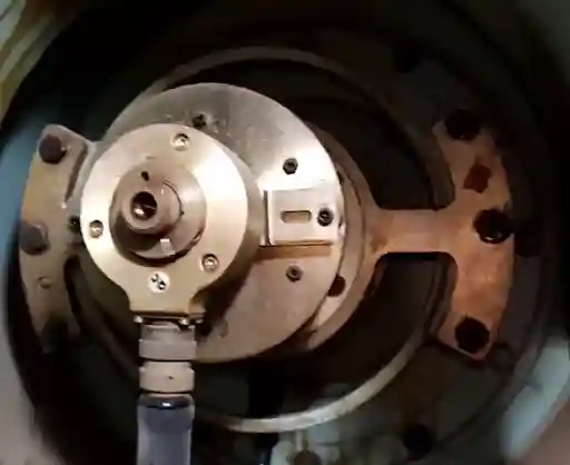
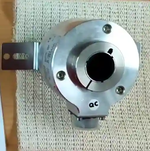
An angle encoder measures the angle of a rotating shaft and outputs an electrical signal. It is connected to the shaft, either directly or using a gear/ belt drive system.

Types of angle encoders:-

  1. Incremental: These output pulses. The control will count these pulses to determine how far around the shaft has travelled. They will need to have a reference point (one pulse per revolution) to know ‘zero’. When there is a loss of power the count will be lost and they will need to find the reference point again.
  2. Absolute: Each angle will have an individual code. They can be used to know exactly what angle the shaft is at at any given time. There is no counting involved and there is no need for a reference point. If there is a loss of power and then power is restored they know the position straight away. This is a big benefit for engine control.

Most absolute encoders use an optical/magnetic wheel with a coded pattern and sensors to detect the position. The position is output as a digital signal and usually uses a serial interface.

Learn More with the Merchant Navy Decoded App

Want to improve your practical marine engineering knowledge? Explore the Merchant Navy Decoded App, where seafarers can access MND FLIX technical learning resources, MMD exam preparation support, DG Shipping updates, and other useful maritime services.

Explore the Merchant Navy Decoded App

Angle Encoders on Ships

The most common use of angle encoders is the main engine crank angle. However there are a lot of applications for angle encoders and angle sensors on ships:-

  1. Main engine crank angle/speed 
  2. Rudder angle indicators/transmitter – To let the bridge know what rudder angle is applied.
  3. Controllable pitch propeller pitch feedback.
  4. Azimuth thruster angle.
  5. Crane slewing/luffing angle.
  6. Turbocharger and Shaft speed.
  7. Valve position feedback on rotary actuators.

The same principle applies throughout, the angle is measured and converted into a signal to send to the controller.

Table of Contents

RT-flex Absolute Angle Encoder

RT-flex Absolute Angle Encoder

As there is no camshaft on the RT-flex engine, the fuel injectors and exhaust valves are opened/closed using electronic control and hydraulics (servo oil). The control system (WECS – Wärtsilä Engine Control System) will control when each cylinder will inject fuel and open/close its valves. It therefore needs a very accurate and reliable source for the crank angle.

Function:-

The crank angle sensor unit provides the WECS with the angular position of the crankshaft. This is then used by the control modules to time:-

  • Fuel injection start and end
  • Exhaust valve opening/closing
  • Starting air valve operation.
  • Engine speed (RPM) for the speed governor

Absolute measurement : The encoder provides a true reading of the crank angle. This means that the position of the crankshaft will always be known. Even at a start up.

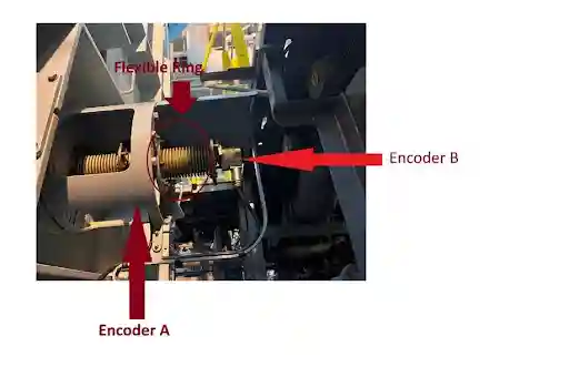
Connection : The angle sensor unit will generally be connected to the free end of the crankshaft. It is driven by the crankshaft using a drive system, typically gears or toothed belt. The exact connection is dependant on the type of engine and generation.

Redundancy : As the angle signal is so important, it is generally duplicated. This means that there are two independent sensor units. The WECS will compare the two readings. If one fails, the engine can still run using the other sensor.

Zero Setting : The zero on the encoder needs to match the actual position of the crankshaft. This is typically set to top dead centre for a specific cylinder. This will be set during commissioning and checked after any work has been carried out on encoder, drive or coupling. If this is incorrect, all injection and valve events will be incorrectly timed. After replacing the encoder or drive, the angle needs to be checked against the engine markers. Refer to manufacturers procedures.

Common issues:-

  • Drive problems – Belt worn/slip, loose coupling or damaged gears. This will result in loss of position.
  • Signal issues – Damaged cables, loose connections or damp.
  • Contamination – Oil mist or dirt.
  • Sensor unit damaged due to vibrations.
  • Incorrect zero setting after maintenance.
  • Alarms for both sensors not matching indicate a fault with one of the sensors.

The exact issues will vary depending on the type of engine and software type. Always refer to the manufacturers manual for the specific engine.

Manoeuvre System

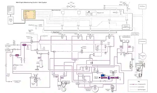
The manoeuvre system allows someone on the bridge/engine control room/local control panel to command the engine to start, stop, ahead, astern and change speed. The command is sent and the correct sequence is carried out.

Main components:-

  • Engine telegraph/control lever – Command sent to the engine (Slow Ahead/Half Ahead/Full Ahead/Stop/Half Astern).
  • Remote control – Takes the command and checks if it is safe to do. Sends commands to the engine.
  • Engine control (WECS for RT-flex) – Controls injection, valve timing and speed governing.
  • Safety – Monitors key parameters and can slow or shut down the engine.
  • Starting air system – Valves and control air.
  • Control panels – Bridge/engine control room/local. There is a changeover system to ensure only one panel has control. Locals can always override.

Overview of process:-

  1. Command is sent from the bridge e.g. Slow Ahead.
  2. Remote control checks interlocks. Turning gear is disengaged, there is enough starting air/control air, engine is ready and no shutdown in place. Fuel and Lube oil systems are running as required.
  3. If all is OK, direction is set and the engine starts on air.
  4. Starting air turns the engine. Once the engine reaches firing speed the WECS will start injecting fuel. Starting air is cut off.
  5. The governor will keep the engine at the requested speed.
  6. If the command changes e.g. ahead to astern there will be a sequence to slow the engine down. If needed the engine will stop. The engine will then be started in the opposite direction. The engine control will electronically change the timing for RT-flex engines.
  7. There are protective features included. If the engine does not start, there will be a set number of attempts before a failure is indicated. If the engine is in a critical speed range it will pass through it quickly. The system will limit the amount of time the engine spends in this area. If there is a safety issue the engine will slow down or shut down depending on the cause. Some can be overridden by the bridge in an emergency.

Control Air for Manoeuvre

Control air is clean dry air used to control the pneumatic components of the manoeuvre and safety system. This is separate to the high pressure starting air.

Typical uses:-

  • To control pilot valves to open the main starting valve and starting air valves.
  • Shut off and safety valves on starting air/fuel systems.
  • Turning gear interlocks and other interlocks.
  • Pneumatic components of remote control – Actuators and some instrument signals.
  • Pneumatic components of safety shutdown.

Air from the main air compressors is sent to the air receivers. Control air is taken from this source using a pressure reducing valve, filter and dryer (Sometimes using a separate control air compressor). This reduces the pressure to a much lower and constant pressure. Typically this pressure will be 6-8 bar. The exact pressure will depend on the engine and ship. There may also be a separate control air receiver or connection to general service air.

Why it is important: If there is no control air or it drops below a certain pressure, the manoeuvre system will not function. The engine may not start. There will therefore be an alarm for the low pressure. Often there will be some interlocks to prevent the engine starting. If there is water, oil or dirt in the control air this can cause freezing, blockages to small orifices and sticking valves.

Common issues:-
  • Low pressure due to faulty pressure reducing valve, leakage or faulty compressor.
  • Water in the air due to faulty dryer or blocked drain.
  • Blocked filters.
  • Leakage from connections/pipes.
  • Sticking valves due to contamination.

Best Practice:-

  • Drain the receivers and moisture traps regularly.
  • Check the dryer and filters as required.
  • Check the low pressure alarm.
  • Check the control air pressure before every arrival/departure.
  • Consider control air a critical component. Without it you may not be able to start/manoeuvre.

Manoeuvre Diagram

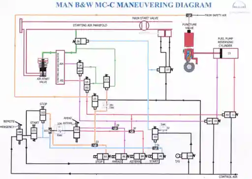
A manoeuvre (or manoeuvre system) diagram shows how the command from the bridge is sent to the engine. Usually it shows the pneumatic circuit, interlocks and control logic on one page. The diagrams will vary depending on the engine however they will all have the same logic. 

How to read:-

  1. Start by looking at the command: Locate the telegraph/control lever at the top.
  2. Look at the logic: The remote control system will be in the middle. Look for the interlocks coming into it. If none of these are met the engine cannot be started.
  3. Look for the control air: Thin pilot lines from the control air source to the pilot valves. These control the main components but do not carry the main air.
  4. Look for the starting air: Thick lines from starting air receivers to main starting valve and engine. This is the air that will turn the engine.
  5. Look for feedback: Angle encoder and speed signals will be sent back from the engine to the control. On a mechanical engine this will be done by the air distributor and timing components. On an RT-flex it will be the angle encoder.
  6. Look for the cut off: Shows when the starting air is cut off once the engine has fired. If the engine does not start.
  7. Look for shutdown/slowdown: Lines for shutdown and slowdown will be shown to feed back and cut fuel or ask for a slower speed.

A manoeuvre diagram can also refer to the table showing engine speeds for each telegraph setting (Dead Slow/Slow/Half/Full). RPM and if fitted pitch settings. If this is what you are referring to, the principle is simpler. Each telegraph setting will correspond to a speed setpoint. The control will make the engine match this speed.

Always refer to your engines manoeuvre diagram in the manual. The exact valves, interlocks and sequence will vary.

Manoeuvring Diagram

Common Problems:-

  • Engine does not start – Low starting/control air, turning gear interlock, sticking valve or loss of angle signal.
  • Leakage from starting air or faulty main starting valve.
  • Incorrect direction or no response from telegraph – Faulty remote control/command.
  • Engine slows/shuts down during manoeuvre – Safety issue e.g. low lube oil pressure.
  • Issues with control panels.
  • Fault with angle encoder/speed signal – Engine may not start/run.
  • Water in control air causing sticking valves.


Best Practice:-

  • Test manoeuvre system before arriving/departing. Ensure you can start ahead/astern from each of the control panels. As per ships procedures.
  • Check starting air/control air pressure before manoeuvre.
  • Ensure turning gear is disengaged and interlocked.
  • Ensure air systems are drained and dryers working.
  • Know your engine’s critical speed ranges and avoid getting stuck in them.
  • Take any alarms from the angle encoder seriously. Never ignore alarms for sensors not matching.
  • After any work has been carried out on the encoder/drive, ensure the calibration is correct using manufacturer procedures.
  • Have the manoeuvre diagram to hand. Know where the interlocks are coming from.

Conclusion

The angle encoder lets the engine know what position it is in. The manoeuvre system takes the command from the bridge and safely starts the engine, changes direction and keeps the engine at a constant speed. The control air supply keeps the pilot valves, shutdown valves and interlocks alive. If you learn how to read the manoeuvre diagram from the telegraph to the main starting valve and back using the angle feedback, you will understand why a lot of the time a failed start will be due to an interlock not being met, low control air or loss of angle signal.

Frequently Asked Questions (FAQs)

It measures the angle of a rotating shaft and provides an electrical signal to the controller.

An incremental encoder will provide pulses. They need to be counted and will require a reference point. An absolute encoder will provide a unique code for each position meaning they know the angle instantly. Even if there is a loss of power.

As there is no camshaft, the electronic control system needs to know the exact crank angle to time the fuel injection, exhaust valves and starting air.

To provide redundancy. The control will compare the two. If one fails the engine can still run using the other.

All injection and valve events will be incorrectly timed. The engine may not run correctly or may not start. The zero should be checked after any work has been carried out on the encoder/drive.

To control the pilot valves, shut off/safety valves, interlocks and other pneumatic components. This is separate to high pressure starting air.

The manoeuvre system may not function meaning the engine may not start. There will be an alarm for the low pressure. There will usually be an interlock preventing the engine from starting.

Typically the turning gear will need to be disengaged, there will need to be enough starting/control air, no active shutdown and the required systems will be running. Refer to your engine’s manual for exact requirements.

Start by looking at the command, look for the interlocks, control air to the pilot valves, starting air to the engine, feedback signals, cut off and safety.

Disclaimer :- The opinions expressed in this article belong solely to the author and may not necessarily reflect those of Merchant Navy Decoded. We cannot guarantee the accuracy of the information provided and disclaim any responsibility for it. Data and visuals used are sourced from publicly available information and may not be authenticated by any regulatory body. Reviews and comments appearing on our blogs represent the opinions of individuals and do not necessarily reflect the views of Merchant Navy Decoded. We are not responsible for any loss or damage resulting from reliance on these reviews or comments.

Reproduction, copying, sharing, or use of the article or images in any form is strictly prohibited without prior permission from both the author and Merchant Navy Decoded.

DIWALI SALE

Decoded Discount Alert! up to 50% OFF

DIWALI SALE

Decoded Discount Alert! up to 50% OFF

Use Coupon Code Deep50

Days
Hours
Seconds
0
Would love your thoughts, please comment.x
()
x