Hi this is Team Merchant Navy Decoded !!!
Please fill the below form with your query and we will get back to you in next 12 hours.
Rest assured your data is safe with us !!!🙂
Ask Your Query| For Beginner | For Professional |
|---|---|
| GME | Engine Side |
| G.P. Rating | Deck Side |
| ETO | G.P. Rating |
| IMUCET & Sponsorship | Combo Offers |
| Free Course | MEO |
| Free Course |
| For Beginner | For Professional |
|---|---|
| GME | Engine Side |
| G.P. Rating | Deck Side |
| ETO | G.P. Rating |
| IMUCET & Sponsorship | Combo Offers |
| Free Course | MEO |
| Free Course |
Most electrical equipment onboard are powered by Alternating Current. Main Switchboards, Pumps, Lighting, Galley and Thrusters will all be powered by AC. There may be some instances where Direct Current will be used (Batteries, Control Circuits and Emergency Systems), however the main equipment will be powered by AC. It is important to understand what an AC source is, how they work in a circuit and why they are different from batteries.
Want to understand AC sources and electrical circuits in practical shipboard applications? Explore the Electrical Circuit Diagram Course by Merchant Navy Decoded to strengthen your electrical knowledge.
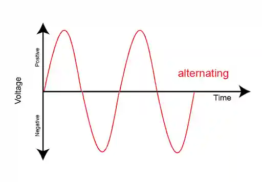
Unlike DC, AC has a voltage and current that will continuously change directions. If we plotted this onto a graph over time, we would see a nice clean sine wave. The voltage will go up to a peak, then down to zero, then become negative to a peak.
With Sine Waves the Peak Value can be calculated by multiplying the RMS value by √2 (approximately 1.414). If our RMS value was 440V our actual Peak Voltage would be approximately 622V. Our insulation and equipment must be rated to cope with this.
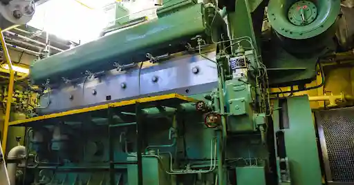
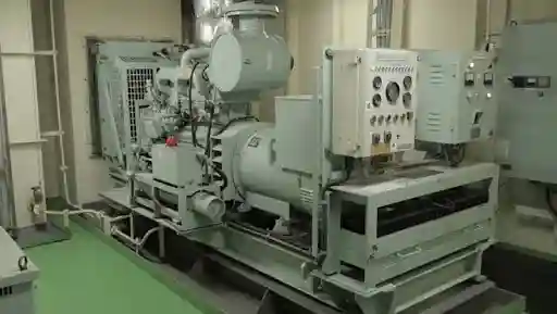
An AC source is any piece of equipment that can provide an Alternating Voltage to a load. Typical AC sources on board include:


reality all AC sources will have some form of internal impedance. This is due to the resistance and reactance of the windings. As the current flows through this impedance there will be a voltage drop. Therefore as the load increases, the voltage at the terminals will reduce.
When a large motor is started there will be a voltage drop on the generators. The AVR will constantly try to increase the excitation to keep a stable voltage. If a generator becomes overloaded there will be a low voltage and low frequency. Resistors, Inductors & Capacitors will all affect the behaviour of the circuit. Real equipment usually consists of all 3.
Heaters, Incandescent Lamps, Galley Elements. The current and voltage will increase and decrease together. They will be in phase. All power will be used for useful work.
Motors, Transformers, Fluorescent Lamp Ballasts. These have coils. Coils resist changes in current so the current will lag behind. This is known as Inductive Reactance. Can be calculated using XL = 2Ï€fL. Frequency will cause this to increase.
Capacitors (Power Factor Correction Banks & some electronic equipment). This will cause current to lead. This resistance is known as Capacitive Reactance. Can be calculated using XC = 1/(2Ï€fC). Frequency will cause this to decrease.
Impedance (Z) is the total resistance to an Alternating Current. Made up of Resistance & Reactance.
There may be a phase difference between the voltage and current. This means there are 3 types of power.
The ratio of Real Power to Apparent Power is known as the Power Factor (Cos φ). If the Power Factor is 1 then all the current is being used for useful work. If the Power Factor is low then a greater current will be required to achieve the same amount of useful power. Generators are rated in kVA. They will have a set Power Factor (usually 0.8). If a generator is rated at 100kVA with a Power Factor of 0.8 it can only provide 80kW of Real Power.
A low Power Factor (usually caused by underloaded motors) will cause more capacity to be used by the generator and cause the cables to heat up. This is why generators will share their load based upon kW & kVAr. The AVRs are important here.
Three Phase windings can be configured as Star or Delta. With Star there are 2 voltages to consider.
With a star connection:-
Line Voltage = √3 x Phase Voltage
If the system is 440V then the phase voltage will be 440 / 1.732 = 254V. The 220V lighting is a separate system and will be provided via a transformer.
Power in a balanced Three Phase Load can be calculated using:-
P = √3 x V(line) x I(line) x Cos φ
Example: Three Phase Motor supplied with 440V and drawing 100A. Power Factor of 0.8.
Apparent Power = 1.732 x 440 x 100 = 76,208VA = 76.2kVA
Real Power = 76.2kVA x 0.8 = 61kW
Before connecting any AC sources (generators, generators & shore supply) together they need to be matched. The incoming source needs to be of the same voltage, frequency & phase as the live busbar. They also need to have the same phase sequence. This can be done using a Synchroscope or Synchronising Lamps. If the breaker is not in sync when closing it will cause a large surge of current. This can cause a mechanical impact on the generator.
Once the sources have been paralleled they will share the load. Real Power will be shared using the engine governors. Reactive Power will be shared using the AVRs.
Best Practice
An AC Source is not just an alternating battery. It has a frequency, phase, internal impedance & power factor. All these will affect how it will behave in a circuit. Generators, Transformers, Shore supply and Inverters all provide the same basic function of providing Alternating Voltage to a load. If you understand RMS/Peak, Resistance/Reactance, kW/kVA & Line/Phase Voltage then most meters on the switchboard will be easy to read.
Any piece of equipment that provides an Alternating Voltage to a circuit. This could be a Generator, Shaft Generator, Shore Supply, Transformer Secondary or Inverter.
This means the Line Voltage between the phases (RMS). The Peak Voltage will be higher. 440 x 1.414 = 622V.
Line Voltage is between 2 phases. Phase Voltage is between a phase and a star point. If the winding is in a Star configuration the Line Voltage will be √3 times larger than the Phase Voltage. In a 440V system the Phase Voltage will be approximately 254V.
The ratio of Real Power (kW) to Apparent Power (kVA). A low Power Factor means more current will be required.
kW – Real Power. Useful Power. kVAr – Reactive Power. Used to create magnetic & electric fields. kVA – Apparent Power. Combines both kW & kVAr. This is what the generator and cables need to be able to handle.
There will be a voltage drop across the internal impedance. The engine will slow down due to the overload.
Voltage, Frequency, Phase & Phase Sequence.
It is efficient, uses less copper and provides a smooth power. Three Phase Motors are robust and can be easily run. Transformers can be used to easily change the voltage.
Disclaimer :- The opinions expressed in this article belong solely to the author and may not necessarily reflect those of Merchant Navy Decoded. We cannot guarantee the accuracy of the information provided and disclaim any responsibility for it. Data and visuals used are sourced from publicly available information and may not be authenticated by any regulatory body. Reviews and comments appearing on our blogs represent the opinions of individuals and do not necessarily reflect the views of Merchant Navy Decoded. We are not responsible for any loss or damage resulting from reliance on these reviews or comments.
Reproduction, copying, sharing, or use of the article or images in any form is strictly prohibited without prior permission from both the author and Merchant Navy Decoded.
Decoded Discount Alert! up to 50% OFF
Use Coupon Code Deep50