Hi this is Team Merchant Navy Decoded !!!

Please fill the below form with your query and we will get back to you in next 12 hours.

Rest assured your data is safe with us !!!🙂

Ask Your Query

Different types of pressure transmitters and switches

Different types of pressure transmitters and switches

Some pressure transmitters will just read the pressure within the system while others will read the pressure drop. If a fuel filter was becoming blocked, there would be no pressure change inside the tank but the pressure difference would increase. This is what a differential pressure transmitter will read. There are lots of pieces of equipment on board that are monitored by a differential pressure transmitter.

This post will look at the different types of pressure transmitter and switch, and also will take a closer look at differential pressure transmitters, how they work, where they are used and how to calibrate.

Want to understand how Pressure Transmitters and Pressure Switches work onboard ships? Explore the Automation Package by Merchant Navy Decoded to learn about sensors, transducers, pressure switches, differential pressure transmitters, and their practical applications in shipboard automation systems.

Types of pressure transmitter

Types of pressure transmitter
  • Gauge pressure transmitter: These measure pressure relative to the atmosphere. This is the most common type of transmitter found. They are found on lube oil, fuel, jacket water, air and hydraulic lines.
  • Absolute pressure transmitter: These measure pressure relative to a sealed vacuum. They are used where we don’t want atmospheric pressure affecting the reading such as vacuum systems and certain steam and condenser readings.
  • Differential (DP) pressure transmitter: These measure the difference in pressure between two points. This is what we’ll be looking at.
  • Sealed gauge pressure transmitter: These are similar to gauge transmitters but are measuring pressure relative to a known pressure. Usually for higher ranges.

Types of pressure switches:-

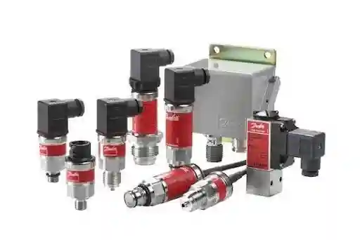
  • Pressure switch – Alarm/trip when pressure reaches a certain value. Can be rising or falling.
  • Vacuum switch and differential pressure switch – Trip when pressure difference between two points reaches a certain value. Can be mechanical using a diaphragm/piston/bellows and micro switch or electrical using a sensor and programmable output.

How differential pressure transmitters work

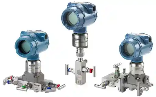
A differential pressure (DP) transmitter will have two pressure connections. Usually labelled H (high) and L (low). Inside the transmitter there will be a sensing diaphragm between two chambers. The high pressure will be acting on one side of the diaphragm and the low pressure on the other side.

The difference in pressure is what matters. If both sides are reading 5bar then the diaphragm will not move and the transmitter will read 0. If the high pressure is reading 5.4bar and the low pressure is reading 5bar then there is a 0.4bar pressure difference. The diaphragm will move a little and the transmitter will read accordingly.

This small movement is picked up in the same way as other transmitters. The most common ways are using a capacitive cell where the diaphragm moves between two plates causing a change in capacitance. Or a piezoresistive element where the strain gauges on the diaphragm change resistance. The transmitter will amplify and condition the signal and give a 4-20mA signal. 4mA will be the lowest point and 20mA will be the highest. Many transmitters will also have a digital protocol (such as HART) to allow them to be configured.

Whilst the transmitter may be reading 0.4bar difference, both sides may be receiving a high line pressure (such as 10/20bar). A quality DP transmitter will be able to cope with this high static pressure and will still be able to detect this small difference. If only one side was over pressurised (for example by incorrectly opening a valve) then the diaphragm could be damaged. Therefore, it is very important to follow the correct valve sequence.

Table of Contents

Where are differential pressure transmitters used?

There are many places differential pressure can be used:-

  • Filter/strainer monitoring: The pressure before and after the filter will tell us how clogged it is. As the filter gets clogged the pressure difference will increase. Often fuel oil filters, lube oil filters and automatic back flushing filters will use a DP switch or transmitter to alarm or flush.
  • Level monitoring: The pressure difference between the bottom of the liquid column and the vapour will give us an indication of liquid level. This is used on boiler drum level, deaerator level and some tanks.
  • Flow monitoring: When there is a restriction in the line (such as an orifice plate or venturi) there will be a pressure drop. The greater the flow the greater the pressure drop. The pressure drop over this will give us the flow rate.
  • Air coolers/heat exchangers: An increasing pressure drop over the charge air cooler or heat exchanger can indicate fouling.
  • Pump/system monitoring: The pressure difference across a pump or valve can tell us if it is functioning correctly.
  • Ventilation/air filters: The pressure difference across the filter/duct will tell us if it is blocked.

Impulse lines and manifolds.

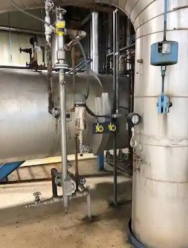
A DP transmitter will not normally be connected directly to the process. They will be connected via small bore impulse lines. Often these will go through a manifold.

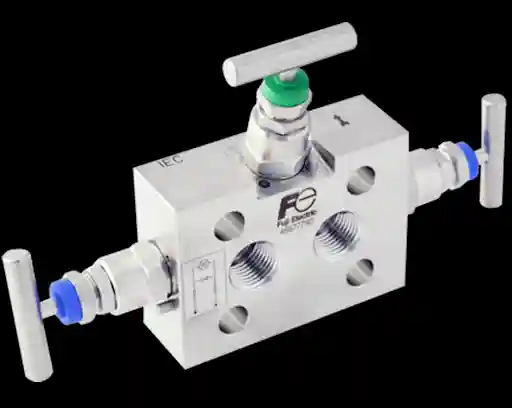
A 3 valve manifold will have two isolation valves (one for each side) and an equalising valve connecting the high and low sides. A 5 valve manifold will have 2 extra valves to vent or drain. It allows us to isolate the transmitter, equalise the high and low sides to check zero and safely vent.

For level monitoring there will be wet legs (reference line filled with liquid) and dry legs (reference line left empty/gas filled). This will affect how the reading is calculated and zeroed. It is important to know what type you have. Impulse lines can become blocked with sludge, trap air/gas or leak. This will cause an incorrect reading. Many issues with faulty transmitters are actually caused by the impulse lines.

How differential pressure switches work.

A differential pressure switch will do the same job as a differential pressure transmitter but will not give a continuous signal. There are 2 pressure connections and the sensing element (diaphragm/piston) will be acted upon by high pressure on one side and low pressure on the other. There is a spring opposing the movement. When the pressure difference overcomes the spring force the element will move and activate the micro switch.

Like any pressure switch, the spring will set the setpoint. There will be a differential (deadband). Often used for alarms on filters. When the pressure difference across the filter reaches 0.8bar the DP switch will trip indicating that the filter needs cleaning/changing. The setpoint will come from the manufacturer or equipment manual.

Calibrating differential pressure transmitters

We want to ensure we have the correct output for the pressure difference across the range. If not, we will need to adjust.

Before calibration

  • Notify the control room and place the loop/alarm into inhibit as per the ships procedure.
  • Isolate the transmitter by closing the isolation valves on the manifold. Safely relieve the pressure difference. Be careful with the valve sequence to avoid putting too much pressure on the diaphragm.
  • Ensure your calibrator, hand pump and hoses are suitable for the range.

Calibration

  1. Zero check: With the isolation valves closed and equalising valve open both sides will be seeing the same pressure (usually atmospheric after venting). The transmitter should be reading 0 differential pressure (4mA). If not, adjust the zero trim.
  2. Connect the calibrator: Connect the hand pump and reference sensor to the high side. Leave the low side vented to atmosphere (or as required). Connect the mA meter to the loop.
  3. Test points: Increase the pressure to approximately 0%, 25%, 50%, 75% and 100% of your calibrated range. Reduce the pressure again. Record your pressure and mA reading.
  4. Compare:  Calculate the mA you should be getting at each point and compare to what you have. Note any errors. There may be some hysteresis.
  5. Adjust: Firstly adjust the zero, then adjust the span. Recheck as they can affect each other. With smart transmitters use the handheld configurator to trim.
  6. Record your as found and as left values: Ensure they are within tolerance.
  7. Check for leaks: Where required, check for static pressure. There may be some zero shift if both sides are seeing high line pressure. Sometimes a static pressure zero check will be performed.
  8. Reconnect: Close the equalising valve. Open the isolation valves in the correct sequence. Usually the equalising valve will be opened first. Then the high side. Then the low side. Close the equaliser. Follow the ships procedure and type of manifold. Remove the loop from inhibit. Confirm with the control room.

Make sure you follow the valve sequence. At all times we don’t want the diaphragm to see a large pressure difference.

Calibrating a differential pressure switch.

  1. Isolate and inhibit as above: If possible remove the switch.
  2. Connect the pump and reference gauge to the high side Leave the low side vented (or as required for the test). Connect a multimeter across the contacts.
  3. Slowly increase the pressure until the contacts change. Note the pressure. This is the trip point.
  4. Slowly reduce the pressure until the contacts change again. Note the pressure. This is the reset point. The difference between the two is the differential.
  5. Compared to required setpoint/tolerance.
  6. If required, adjust the setpoint screw. Repeat a couple of times to confirm the result is repeatable.
  7. Record your as found and as left values. Reconnect the switch. Remove the alarm/trip from the inhibitory.

A common error is to rush. If you increase the pressure quickly the switch may seem to trip at a higher pressure.

Common issues

  • Blocked or partially blocked impulse lines (sludge, dirt, crystals).
  • Air/gas trapped in liquid impulse line or liquid in dry leg: Reading will be fluctuating/noisy.
  • Leaking connections/valves on the manifold: Pressure will be different on one side.
  • Incorrect valve sequence: Diaphragm will be overloaded.
  • Zero drift due to age temperature or overpressure.
  • Wiring issues: Loose terminals or damp junction box.
  • Incorrect range or high/low sides mixed up. After replacing the instrument.

Safety

There can be injury if pressure is trapped on one side. Isolate, vent and prove the instrument is de-pressurised before disconnecting. Use test equipment suitable for the pressure. Don’t exceed the instrument’s limits on either side. Follow permit to work/isolation. Notify the control room before inhibiting any alarms/trips. Ensure they are reconnected. Extra care should be taken on steam, hot oil and high pressure systems.

Conclusion

There are different pressure instruments to answer different questions. Gauge and absolute transmitters will tell us the pressure. A differential transmitter/switch will tell us how much pressure is being lost or how high the level is or how much flow there is. This is why they are used on filters, boilers, coolers and flow lines. Understanding the high and low sides, treating the manifold and impulse lines with care, calibrating to a good reference and recording your results means you can trust a differential pressure reading.

Frequently Asked Questions (FAQs)

Measures the pressure difference between 2 pressures. The output will be proportional to this, usually in a 4-20mA signal.

Filters/strainers, boiler drum level, tank level, flow measurement (orifice plates), air coolers/heat exchangers, ventilation filters.

Gauge measures pressure relative to the atmosphere. Absolute measures pressure relative to a vacuum. Differential measures the pressure difference.

Has 2 isolation valves and 1 equalising valve. Allows you to isolate the transmitter, equalise the high and low sides to check zero and avoid applying uneven pressure to the diaphragm.

Used for level measurements. Wet legs are filled with liquid. Dry legs are left empty/gas filled. This affects how the reading is calculated and zeroed.

Isolate. Open equalising valve. Both sides will be seeing the same pressure. Should read 0 differential (4mA).

If you open/close the valves in the wrong sequence there will be a large pressure difference across the diaphragm and may damage it.

A switch will only change the contacts when the pressure difference reaches a certain value whereas a transmitter will give a continuous signal.

The small bore lines can become blocked with sludge, trap air/gas or leak. This will change the pressure reaching the transmitter.

Disclaimer :- The opinions expressed in this article belong solely to the author and may not necessarily reflect those of Merchant Navy Decoded. We cannot guarantee the accuracy of the information provided and disclaim any responsibility for it. Data and visuals used are sourced from publicly available information and may not be authenticated by any regulatory body. Reviews and comments appearing on our blogs represent the opinions of individuals and do not necessarily reflect the views of Merchant Navy Decoded. We are not responsible for any loss or damage resulting from reliance on these reviews or comments.

Reproduction, copying, sharing, or use of the article or images in any form is strictly prohibited without prior permission from both the author and Merchant Navy Decoded.

DIWALI SALE

Decoded Discount Alert! up to 50% OFF

DIWALI SALE

Decoded Discount Alert! up to 50% OFF

Use Coupon Code Deep50

Days
Hours
Seconds
0
Would love your thoughts, please comment.x
()
x