HPS Construction: Inside the Hydraulic Power Supply of an Electronically Controlled Engine
Every electronically controlled engine covered in this series, the fuel injection, the exhaust valve actuation, the accumulator that smooths it all out depends on one system quietly doing the actual physical work behind the scenes: the Hydraulic Power Supply, or HPS. It’s the unit that turns the engine’s own mechanical drive, plus a bit of electrical backup, into a steady, controlled flow of high-pressure oil. Everything downstream of it the FIVA valves, the fuel boosters, the exhaust actuators is really just spending the pressure the HPS built.
Given how much rides on it, it’s worth going through properly, piece by piece, rather than treating it as one black box between the engine and the fuel system.
What the HPS Actually Consists Of
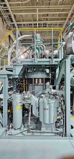
Strip an HPS unit down to its major parts and you’re left with six things: a filter unit, a set of electrically driven start-up pumps, a set of engine-driven pumps, a safety and accumulator block, the high-pressure piping connecting it all, and a drip pan fitted with leak sensors underneath. Every one of those pieces earns its place, and none of them do their job in isolation the filter protects the pumps, the pumps build the pressure, the accumulator block smooths it out and guards against overpressure, and the leak sensors quietly watch for the one thing nobody wants happening under a running engine: high-pressure oil escaping somewhere it shouldn’t.
The Filter
Before oil ever reaches a pump, it goes through the HPS filter unit commonly a Boll or Kanagawa type, both multi-cartridge and self-cleaning. The cleaning itself is done with compressed air, backflushing each cartridge in turn, either on a timer or whenever the pressure drop across the filter climbs past a set point. That second trigger matters more than it sounds; a filter that’s actually getting dirtier than expected backflushes itself more often automatically, rather than waiting for a scheduled interval that might not match real conditions.
There’s also a redundant filter sitting in parallel, there specifically so the main filter can be overhauled without shutting anything down. Switching between the two is done manually, through a butterfly valve that stays closed during normal running and only opens when someone deliberately swaps over and the swap itself doesn’t interrupt oil flow to the pumps while it happens.
Startup
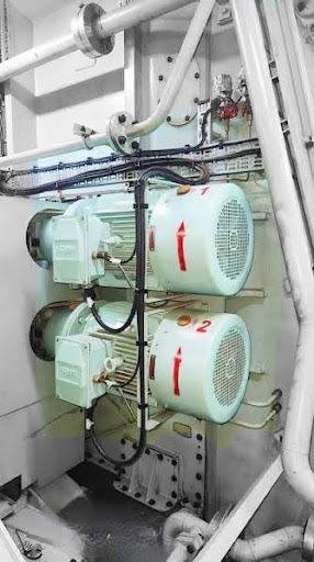
An engine that isn’t turning yet can’t build hydraulic pressure off its own crankshaft, which is exactly the problem the electrically driven start-up pumps solve. There are usually two of them, running at a fixed flow rate rather than the variable output the main pumps use, and their job is simply to get the system up to working pressure before the engine is running, and to back it up if needed once it is. Each pump has its own pressure relief valve, set at the factory to protect the system from overpressure. A typical arrangement might set that relief point somewhere in the 175 to 225 bar range, though the exact figures vary by engine and installation.
These pumps can be run in either Auto or Manual mode. In Auto, the system starts them on its own once the engine’s put into standby and brings pressure up to the required set point before anything else is allowed to proceed. Manual mode exists for exactly the situations you’d expect troubleshooting, maintenance, or a fault elsewhere that needs a human decision rather than an automatic one.
Engine-Driven Pumps
Once the engine is actually turning, the job shifts over to the engine-driven pumps — typically three to five of them depending on engine size, all identical, all of the axial piston type. They’re sized with real redundancy in mind: lose one pump entirely, and the remaining units are still designed to supply enough hydraulic power to keep the engine running at a meaningful fraction of full load, commonly cited around two-thirds, rather than leaving the engine stranded the moment a single pump drops out.
Drive
The engine-driven pumps don’t just sit there waiting for oil to flow through them; they’re mechanically driven off the engine itself, through a gearbox arrangement that ties their rotation directly to crankshaft speed. That’s a deliberate design choice, but it does create a problem worth noticing: engine speed varies constantly, from dead slow manoeuvring up to full sea speed, and a pump spinning proportionally faster or slower with the engine can’t just be a simple fixed-output design and still deliver the steady pressure the fuel injection and exhaust valve systems actually need. That mismatch is exactly why these pumps are built as variable-displacement axial piston units in the first place, which brings us to the swash plate.
Pressure Control Using the Swash Plate
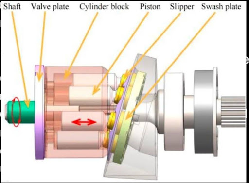
An axial piston pump’s output isn’t fixed by its rotational speed alone; it’s also controlled by the angle of an internal swash plate, which determines how far each piston strokes on every revolution. Tilt the swash plate further, and each piston moves more oil per stroke; bring it back toward flat, and the pump delivers less, even while spinning at exactly the same engine-driven speed. That’s the mechanism that lets these pumps deliver a controlled, steady pressure despite being driven at a constantly changing RPM.
The angle itself is set through a pilot valve acting on the swash plate, with feedback sensors on both the pilot valve and the swash plate position confirming the actual angle matches what’s being commanded, not just assuming it does. Among the pumps running at any given time, one is generally designated the control pump, running continuously around 50% capacity specifically so it has headroom to swing up or down quickly and absorb sudden pressure fluctuations, while the others follow along in what’s usually called follow mode.
There’s a genuinely thoughtful fail-safe built into this arrangement too. If electrical power is lost and the swash plate can no longer be actively controlled, the pump doesn’t just freeze in whatever position it happened to be in; it defaults to maximum output in the ahead direction. Given the alternative is losing hydraulic pressure entirely with the engine still running, defaulting to ahead rather than astern or neutral is exactly the fail-safe direction you’d want.
Sensors
An HPS is genuinely thick with sensors, and for good reason a hydraulic system running at a couple hundred bar with no direct human eyes on the internal oil path needs to report its own condition constantly. Suction pressure sensors confirm the pumps are actually getting fed properly rather than starving. Swash plate position and pilot valve feedback sensors, already mentioned, confirm commands and actual pump output genuinely match. Pressure sensors on the safety and accumulator block report the actual system rail pressure, which the engine control system checks before it ever permits fuel injection to proceed. And the leak sensors sitting in the drip pan below the whole unit are there for exactly one purpose: catching a developing oil leak before it becomes a serious one.
Safety and Accumulator Valve Block
This is where the HPS’s output actually gets regulated and protected before heading out to the rest of the system. The accumulator inside this block works a lot like a hydrophore you’d find in a domestic water system : A nitrogen-filled bladder with a poppet valve controlling oil in and out. With no oil present, the nitrogen keeps that poppet valve shut; as oil enters, it compresses the bladder and the valve opens to let more in, until oil pressure and nitrogen pressure reach balance. If system pressure then drops for any reason, the compressed nitrogen bladder pushes oil back out to compensate, which is exactly what damps out the pressure spikes and dips that would otherwise come from the fuel injection and exhaust valve systems drawing oil in short, sharp bursts. The safety valves in the same block are the last line of defence against genuine overpressure, venting before anything in the system is put at real risk.
Table of Contents
How to Manually Change the HPS Pressure
Most of the time, HPS pressure isn’t something anyone touches directly in Auto mode, the engine control system sets the pressure target itself based on engine load, and the engine-driven pumps’ swash plates adjust to hit it without anyone needing to intervene. Manual adjustment mostly comes up in two contexts:-
First, during maintenance or dry-docking, the start-up pumps’ pressure relief valves sometimes need adjusting if they’re found to be set incorrectly this is routine calibration work, not something done casually, since getting it wrong risks exactly the alarms and pressure fluctuations (or worse, an engine slowdown) that a correctly set relief valve exists to prevent.
Second, the system itself can be run in Manual mode rather than Auto, letting an engineer hold a fixed pressure setting rather than one that automatically tracks load useful for troubleshooting, but not something to leave engaged longer than the situation actually calls for.
A bypass valve’s job, wherever it shows up in the HPS, is to give oil somewhere else to go when its normal path becomes restricted and the clearest example is the filter bypass already touched on earlier. If the main filter starts to clog and the pressure drop across it climbs too high, a bypass path opens so oil keeps reaching the pumps rather than starving them while the filter gets serviced or backflushed. The same underlying logic: Protect the downstream components from being cut off, even if it means momentarily running less-filtered oil shows up anywhere else a bypass arrangement is fitted in the system. It’s not there to be used routinely. It’s there so a developing problem elsewhere doesn’t cascade into pump damage on top of whatever caused it in the first place.
Conclusion
None of these nine pieces work in isolation that’s really the point of walking through them one at a time rather than treating “the HPS” as a single unit. The filter protects everything downstream of it.
The start-up pumps bridge the gap before the engine can drive its own pumps. The engine-driven pumps, controlled through their swash plates, deliver a steady pressure despite a constantly changing drive speed. The safety and accumulator block smooths out what the fuel and exhaust systems throw back at it and stands guard against overpressure. And the sensors scattered through all of it are what let the whole system report honestly on its own condition, rather than anyone having to guess. Understand each piece on its own, and the HPS stops being a sealed box between the engine and the fuel system, and starts being something you can actually troubleshoot.
The engine-driven pumps can’t build hydraulic pressure until the engine itself is turning, so electrically driven start-up pumps are needed to bring the system up to working pressure beforehand, and to back it up if required once the engine is running.
The swash plate’s angle determines how far each piston in the pump strokes on every revolution a steeper angle moves more oil per stroke. This lets the pump deliver a controlled, steady pressure even though it’s mechanically driven at a constantly changing speed tied to engine RPM.
It defaults to maximum output in the ahead direction, a deliberate fail-safe choice, since losing hydraulic pressure entirely while the engine is still running would be a worse outcome than the pump defaulting to full ahead output.
It absorbs and smooths out the pressure fluctuations caused by the fuel injection and exhaust valve systems drawing oil in short bursts, using a nitrogen-filled bladder that compresses as oil enters and pushes oil back out if system pressure drops, working much like a hydrophore.
Mainly during maintenance or dry-docking, if a start-up pump’s pressure relief valve is found to need recalibration, or when deliberately running the system in Manual mode for troubleshooting rather than letting the engine control system set pressure automatically based on load.
Disclaimer :- The opinions expressed in this article belong solely to the author and may not necessarily reflect those of Merchant Navy Decoded. We cannot guarantee the accuracy of the information provided and disclaim any responsibility for it. Data and visuals used are sourced from publicly available information and may not be authenticated by any regulatory body. Reviews and comments appearing on our blogs represent the opinions of individuals and do not necessarily reflect the views of Merchant Navy Decoded. We are not responsible for any loss or damage resulting from reliance on these reviews or comments.
Reproduction, copying, sharing, or use of the article or images in any form is strictly prohibited without prior permission from both the author and Merchant Navy Decoded.