Hi this is Team Merchant Navy Decoded !!!

Please fill the below form with your query and we will get back to you in next 12 hours.

Rest assured your data is safe with us !!!🙂

Ask Your Query

PLC Programming for Ship Automation Systems

PLC Programming for Ship Automation Systems

The PLC listens to the ship through input modules and talks back through output modules. What actually decides what to do with a bilge float switch closing, or when to energise a standby generator’s start contactor, is the program running inside the controller. That program is where boiler three-element control, generator auto-start interlocks, and ballast valve sequencing all actually live  and it’s worth understanding both how that logic is written and how it’s safely handled on board, since a badly made change to a running automation program is a very different kind of risk than a badly made change to, say, a spreadsheet.

How the Program Actually Runs: The Scan Cycle

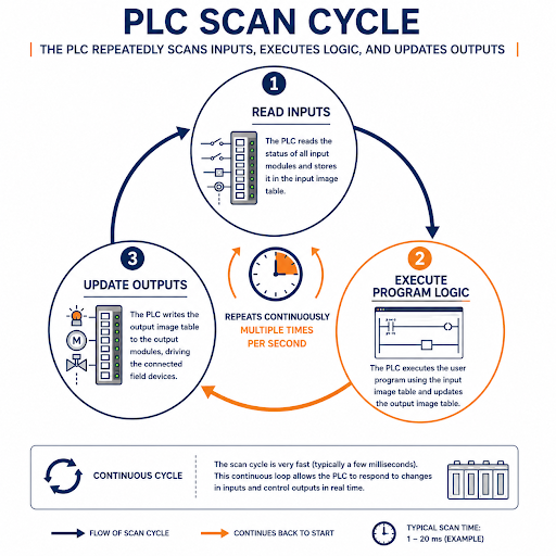
PLC Scan Cycle

A PLC doesn’t run its program continuously the way a general-purpose computer runs software  it works in a repeating scan cycle: read all inputs, execute the entire program logic against those input values, update all outputs, and repeat, typically many times per second. This matters practically: a change in a field device’s state is only ever as current as the most recent scan, and program logic is written with the understanding that it will be evaluated fresh, top to bottom, on every single cycle rather than running once and waiting.

Quick pointer: If a change on the bridge or in the engine room seems to lag slightly before an automated response happens, the scan cycle is a normal part of that genuinely faulty logic and simple scan timing look similar at first glance, so it’s worth ruling out the latter before assuming the former.

The Standard Languages: IEC 61131-3

The Standard Languages

Almost all industrial and marine PLC programming today is written in one of the languages defined by IEC 61131-3, the international standard covering PLC programming  chosen because it lets logic be documented and, in principle, understood across different manufacturers’ platforms, even though most vendors add their own extensions on top.

  • Ladder Diagram (LD) is the most widely used, and for good reason on a ship: it visually resembles the relay wiring diagrams it replaced, reading left to right across horizontal “rungs” between two vertical power rails. A generator auto-start interlock checks running generator’s load, checks standby generator’s readiness, energises the start contactor  reads naturally as a ladder rung to anyone who’s traced physical relay wiring before.
  • Function Block Diagram (FBD) represents logic as interconnected blocks with signal flow lines rather than rungs, and suits process-style control particularly well  a three-element boiler water level controller, taking water level, steam flow, and feed water flow as inputs and calculating a valve position output, is a natural fit for FBD’s block-and-signal structure.
  • Structured Text (ST) is a textual, Pascal-like language suited to complex calculations, data handling, and conditional logic that would be awkward to represent graphically  useful for something like converting an analog transmitter’s raw signal into an engineering value with scaling and alarm limit checks.
  • Sequential Function Chart (SFC) represents a process as a series of steps and transitions, well suited to batch or sequential operations  a tank cleaning cycle, or a multi-stage engine starting sequence, maps naturally onto SFC’s step-by-step structure.
  • Instruction List (IL), an older assembly-style language, has been deprecated in the current edition of the standard and is now mostly encountered only in legacy programs still running on older vessels rather than in new development.

Most real marine automation programs mix languages  ladder for straightforward interlocking logic, function blocks for control loops, structured text for calculations  using whichever language fits a given piece of logic most naturally rather than forcing everything into one.

Table of Contents

Reading a Simple Marine Ladder Logic Example

Reading a Simple Marine Ladder Logic Example

A standby generator auto-start rung illustrates the pattern well: a rung might have contacts checking “running generator overload” and “standby generator ready” in series, feeding a coil that energises the standby unit’s start command. In ladder terms, that’s a normally open contact for the overload condition, another normally open contact for standby readiness, both needing to be true (current able to flow through both, left to right) before the output coil  the start command activates. Add a normally closed contact for “standby already running” in the same rung, and the logic won’t attempt to start a generator that’s already running, all without a single line of written code.

Quick pointer: When troubleshooting ladder logic on an unfamiliar vessel’s system, trace one rung fully before trying to understand the whole program. Ladder logic is genuinely readable a rung at a time; the difficulty is usually in the sheer number of rungs in a full automation program, not in the logic of any single one.

Program Structure: POUs and Organisation

Well-organised marine automation programs are broken into Program Organization Units (POUs)  programs, function blocks, and functions rather than one enormous continuous script. A function block for “generator auto-synchronise” might be written once and reused for each generator on board, taking different input parameters for each instance rather than duplicating the same logic repeatedly. This matters for maintainability: a fault or improvement found in one function block’s logic can be fixed once and applies everywhere that block is used, rather than requiring the same fix to be found and repeated across scattered copies of near-identical code.

Making Changes Safely: This Isn't Like Editing a Document

Modifying a running automation program on board carries real operational risk, and the discipline around it should reflect that:

  • Never edit a live program on a running, unmanned engine room system without understanding the full consequence of the change. A boiler water level control program, a generator auto-start sequence, or a bilge alarm system is actively protecting the vessel while it runs an incomplete or incorrectly tested edit can silently disable that protection rather than simply failing to compile.
  • Always work from a documented backup before making any change, and confirm that backup is genuinely current, not an outdated version from a previous dry-dock or class survey.
  • Test logic changes offline or in simulation where the platform supports it, before downloading to the live controller, and if that’s genuinely not possible, understand exactly what will happen the moment the change takes effect  including what state field devices will be commanded to on the very next scan cycle.
  • Any change affecting a classed or statutory system engine safety systems, UMS-related alarm and monitoring functions, fire and bilge systems typically requires class society notification or approval, not just a working change; check requirements before modifying rather than after.
  • Keep a genuine change log, noting what was changed, why, when, and by whom, separate from the program backup itself; this is what lets a relieving engineer or a class surveyor actually understand the system’s history rather than just its current state.

Commissioning and Testing

  • Test each modified function in isolation where possible before testing it as part of the full running system, the same discipline used when commissioning a system for the first time.
  • Verify field device response matches expected logic under actual operating conditions, not just simulated input values, since a program that behaves correctly in simulation can still reveal wiring or timing issues once connected to real hardware.
  • Involve the relevant watchkeeping officer or engineer before testing any change that will visibly affect machinery behaviour, so an unexpected response during testing isn’t mistaken for a genuine fault requiring emergency action.
  • Document commissioning test results alongside the change log, giving a clear record that the change was actually verified rather than simply downloaded and assumed correct.

Conclusion

The program running inside a ship’s PLCs is where every input module reading and every output module command actually gets decided by the logic connecting a bilge float switch to an alarm horn, or a boiler’s three measured flows to a calculated valve position. Understanding the standard languages, reading logic a rung or block at a time rather than trying to absorb an entire program at once, and treating changes to a running system with the same seriousness given to any other safety-critical modification on board, is what turns PLC programming from an opaque black box into a genuinely manageable part of shipboard engineering.

Frequently Asked Questions (FAQs)

The scan cycle is the PLC’s repeating process of reading inputs, executing program logic, and updating outputs, many times per second. It means a change in a field device only registers as current as the most recent scan  worth ruling out simple scan timing before assuming genuinely faulty logic when a response seems to lag.

Ladder Diagram is the most widely used overall, largely because it visually resembles the relay wiring diagrams it replaced. However, most real marine automation programs mix languages, function block diagrams for control loops like boiler water level control, structured text for calculations, and ladder for straightforward interlocking logic.

Only with real caution and proper procedure  always work from a current, documented backup, test changes offline or in simulation where possible, and understand exactly what a change will command on the very next scan cycle before downloading it to a live, running system, particularly one operating an unmanned machinery space.

Often yes changes affecting classed or statutory systems, such as engine safety systems or UMS-related alarm and monitoring functions, typically require class society notification or approval rather than just a working, tested change. Requirements should be checked before modifying, not after.

POUs  programs, function blocks, and functions are how well-organised automation programs are structured rather than written as one continuous script. A function block written once for a task like generator auto-synchronising can be reused for each generator on board, meaning a fix or improvement applies everywhere that block is used rather than needing to be repeated across duplicated code.

Disclaimer :- The opinions expressed in this article belong solely to the author and may not necessarily reflect those of Merchant Navy Decoded. We cannot guarantee the accuracy of the information provided and disclaim any responsibility for it. Data and visuals used are sourced from publicly available information and may not be authenticated by any regulatory body. Reviews and comments appearing on our blogs represent the opinions of individuals and do not necessarily reflect the views of Merchant Navy Decoded. We are not responsible for any loss or damage resulting from reliance on these reviews or comments.

Reproduction, copying, sharing, or use of the article or images in any form is strictly prohibited without prior permission from both the author and Merchant Navy Decoded.

DIWALI SALE

Decoded Discount Alert! up to 50% OFF

DIWALI SALE

Decoded Discount Alert! up to 50% OFF

Use Coupon Code Deep50

Days
Hours
Seconds
0
Would love your thoughts, please comment.x
()
x