Hi this is Team Merchant Navy Decoded !!!
Please fill the below form with your query and we will get back to you in next 12 hours.
Rest assured your data is safe with us !!!🙂
Ask Your Query| For Beginner | For Professional |
|---|---|
| GME | Engine Side |
| G.P. Rating | Deck Side |
| ETO | G.P. Rating |
| IMUCET & Sponsorship | Combo Offers |
| Free Course | MEO |
| Free Course |
| For Beginner | For Professional |
|---|---|
| GME | Engine Side |
| G.P. Rating | Deck Side |
| ETO | G.P. Rating |
| IMUCET & Sponsorship | Combo Offers |
| Free Course | MEO |
| Free Course |
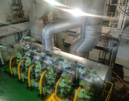
A marine main engine operates under severe conditions involving high combustion pressures, elevated temperatures, rotating machinery, and high-pressure starting air. Failure of an engine component or associated system can result in serious machinery damage, fire, explosion, loss of propulsion, or danger to personnel.
For this reason, modern marine diesel engines are fitted with several dedicated safety devices. These devices provide protection against abnormal pressure, fire propagation, crankcase explosions, incorrect engine operation, and unsafe starting conditions.
The principal main engine safety devices include:
The exact design, arrangement, operating limits, and shutdown logic may vary according to the engine manufacturer.
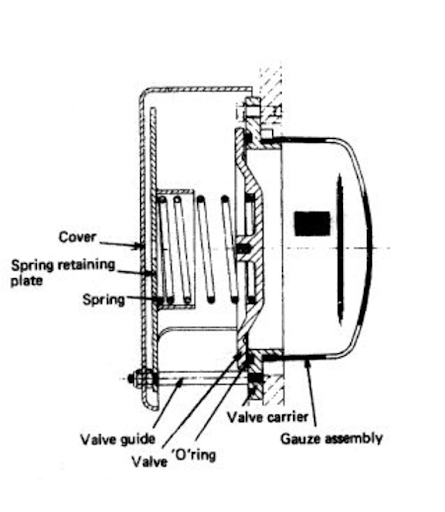
A crankcase pressure relief door, commonly referred to as a pressure relief valve or crankcase pressure relief device, is designed to protect the engine’s crankcase from excessive internal pressure.
During normal operation, the crankcase contains lubricating oil and rotating parts such as the crankshaft, connecting rods, and bearings. If the bearing overheats due to lack of lubrication or mechanical damage, the lubricating oil can evaporate and form a flammable oil mist.
This oil mist can reach flammable concentrations and cause a fire if it comes into contact with hot spots. Combustion can cause a sudden increase in crankcase pressure.
The crankcase pressure relief device is designed to open at a preset pressure and provide a controlled path for pressure relief. This will help prevent the casing from bursting and reduce the severity of the accident.
Modern relief arrangements may incorporate flame-arresting and oil-deflecting features to minimise the discharge of flame and hot gases into the engine room.
The scavenge space relief door is fitted to protect the scavenge air space against excessive pressure.
In a two-stroke marine diesel engine, the scavenge space supplies pressurised air to the cylinder for scavenging and combustion. Under abnormal operating conditions, unburnt fuel, lubricating oil, or carbon deposits may accumulate within the scavenge space.
If these deposits ignite, a scavenge fire may occur. Combustion within the enclosed scavenge space can result in a rapid increase in pressure.
The scavenge space relief device is designed to open when the internal pressure exceeds a predetermined safe value. It allows the excessive pressure to be relieved and protects the scavenge receiver, access doors, and surrounding engine structure from damage.
The cylinder head relief valve, also known as a cylinder safety valve, protects the combustion chamber and associated engine components against excessive cylinder pressure.
During normal combustion, cylinder pressure rises to a high value. However, abnormal conditions can produce pressures exceeding the structural design limits of the cylinder components.
Possible causes of excessive cylinder pressure include:
If cylinder pressure rises above the valve’s predetermined setting, the relief valve opens and allows the excessive pressure to escape. When the pressure falls below the closing value, the valve reseats.
This protection helps prevent damage to the cylinder head, piston, connecting rod, cylinder liner, and other components.
The starting air relief valve is installed in the starting-air system to protect the system against excessive pressure.
Marine main engines are normally started using compressed air stored at high pressure. The starting-air system includes air bottles, pipelines, starting valves, distributors, and associated control equipment.
Abnormal pressure can develop due to equipment malfunction, pressure accumulation, or other faults within the system. Excessive pressure may damage pipelines, valves, and connected components.
The relief valve is set to open when system pressure exceeds its specified operating limit. Excess pressure is then discharged through the designated relief arrangement.
The valve automatically closes when the pressure returns to an acceptable range.
The starting air line flame trap, also known as a flame arrester, is fitted in the starting-air system to prevent the propagation of flame through the starting-air piping.
Under certain abnormal conditions, oil or combustible vapours may be present in the starting-air line. If ignition occurs, the resulting flame can travel through the pipeline and create a dangerous explosion.
The flame trap is designed to interrupt or restrict the passage of flame by absorbing heat and reducing the flame temperature below that required to sustain combustion.
The arrangement helps prevent the flame front from travelling through the starting-air system and reaching other components.
The oil mist detector (OMD) is one of the most important protective devices fitted to a marine main engine.
Its purpose is to continuously monitor the atmosphere inside the crankcase for the presence and concentration of lubricating oil mist.
A damaged or overheated bearing can create a local hot spot. When lubricating oil comes into contact with the overheated surface, it may vaporize and subsequently condense to form fine oil mist particles.
An increasing concentration of oil mist is a serious indication of abnormal internal engine conditions and may precede a crankcase explosion.
The oil mist detector samples the crankcase atmosphere and compares the measured oil mist concentration with the normal operating condition. If the concentration exceeds the alarm limit, the system activates an alarm. Depending on the engine manufacturer’s protection philosophy, a severe condition may also initiate an engine slowdown or shutdown.
The oil mist detector therefore provides early detection, allowing the engineering crew to investigate the cause before ignition or explosion occurs.
The rotation direction interlock, also called the running direction interlock, ensures that the engine is correctly configured for the selected direction of rotation before starting.
Marine propulsion engines may be required to operate in the ahead or astern direction. In reversible engines, the engine’s reversing mechanism must complete the necessary sequence before starting air or fuel can be admitted.
If the direction-changing mechanism has not reached its correct position, starting the engine could result in incorrect rotation or mechanical damage.
The rotation direction interlock receives confirmation that the reversing mechanism has reached the required ahead or astern position. Only after this confirmation is the starting sequence permitted to continue.
The turning gear interlock is a critical safety arrangement fitted to prevent the main engine from being started while the turning gear is engaged.
The turning gear is used to rotate the engine slowly during maintenance, inspection, and preparation for operation. It allows controlled movement of the crankshaft without using the normal propulsion system.
If the main engine were started while the turning gear remained engaged, severe mechanical damage could occur. More importantly, personnel working near or on the engine could be exposed to serious danger.
For this reason, the turning gear is connected to an interlocking arrangement. When the turning gear is engaged, the starting system is blocked and the main engine cannot be started.
The engine can only be started after the turning gear has been fully disengaged and the interlock confirms the safe position.
The safety devices fitted to a marine main engine provide several layers of protection. Some devices are designed to detect a developing fault, while others act directly to prevent excessive pressure, fire propagation, explosion, or unsafe engine operation.
Their importance can be summarised as follows:
It is important to remember that these devices are safety-critical equipment. They must be maintained, inspected, and tested in accordance with the engine manufacturer’s instructions, classification requirements, and the vessel’s planned maintenance and safety management procedures.
Safety devices should never be bypassed or rendered inoperative without proper authorization and an approved safety procedure.
The principal main engine safety devices include the crankcase relief device, scavenge space relief device, cylinder head relief valve, starting air relief valve, starting air line flame trap, oil mist detector, rotation direction interlock, and turning gear interlock. Their purpose is to protect the engine and personnel from excessive pressure, explosions, fires, and unsafe operating conditions.
A crankcase relief door protects the engine crankcase from excessive internal pressure. In the event of oil mist ignition or a crankcase explosion, the device opens at its designed pressure to relieve the pressure in a controlled manner and reduce the risk of crankcase rupture.
An oil mist detector continuously monitors the crankcase atmosphere for abnormal concentrations of oil mist. Excessive oil mist may indicate overheating of a bearing or another internal component. The detector provides an early warning and, depending on the engine protection system, may initiate an alarm, slowdown, or engine shutdown.
A turning gear interlock prevents the main engine from starting while the turning gear is engaged. This protects personnel and prevents serious mechanical damage to the turning gear, crankshaft, and associated components.
A safety relief valve or relief device protects equipment by releasing excessive pressure when a predetermined limit is exceeded. An interlock, on the other hand, prevents an unsafe operation from taking place, such as starting the engine while the turning gear is engaged or before the correct direction of rotation has been confirmed.
Disclaimer :- The opinions expressed in this article belong solely to the author and may not necessarily reflect those of Merchant Navy Decoded. We cannot guarantee the accuracy of the information provided and disclaim any responsibility for it. Data and visuals used are sourced from publicly available information and may not be authenticated by any regulatory body. Reviews and comments appearing on our blogs represent the opinions of individuals and do not necessarily reflect the views of Merchant Navy Decoded. We are not responsible for any loss or damage resulting from reliance on these reviews or comments.
Reproduction, copying, sharing, or use of the article or images in any form is strictly prohibited without prior permission from both the author and Merchant Navy Decoded.
Decoded Discount Alert! up to 50% OFF
Use Coupon Code Deep50