Hi this is Team Merchant Navy Decoded !!!

Please fill the below form with your query and we will get back to you in next 12 hours.

Rest assured your data is safe with us !!!🙂

Ask Your Query

PLC Input and Output Modules on Ships

PLC Input and Output Modules on Ships

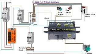
Every marine automation system- boiler water level control, generator auto-synchronising, alarm monitoring runs on a PLC or PLC-based controller somewhere in its architecture. That controller has exactly two jobs at its electrical boundary: Listen to the ship through input modules and act on the ship through output modules.  A bilge float switch closing, a boiler pressure transmitter reporting a value, a fire damper solenoid releasing, a ballast pump contactor energising all of it passes through one of these two module types.

Understanding both halves of that boundary is what turns troubleshooting a shipboard automation fault into a fast, methodical process instead of guesswork.

PLC Input

The Shared Principle: Isolation

 Neither module type connects field-side wiring directly to the PLC’s processor. Field devices – Limit switches, pressure transmitters, solenoid valves, contactors operate at real-world voltages and currents that are neither clean nor safe near sensitive processor circuitry, and engine room electrical environments add moisture, vibration, and switching-induced voltage spikes into the mix. The component doing the actual isolation work, on both input and output modules, is typically an optocoupler: an LED on the field-wiring side and a phototransistor on the processor side, with no direct electrical connection between them. Field-side current or voltage lights the LED, light crosses a physical gap, and the phototransistor switches in response. The processor never sees field-side electrical conditions directly.

Quick pointer: Every channel’s status LED is your fastest diagnostic tool. A lit input LED with no logic response, or a lit output LED with the field device not responding, immediately tells you the fault is on the other side of that isolation boundary from where the module itself sits, saving you from chasing the wrong half of the circuit.

Digital Input Modules: Detecting On/Off

Digital Input Module

A digital input channel answers one question: is the field device open or closed? Aboard ship this covers bilge high-level float switches, watertight door position switches, fire damper limit switches, and generator breaker status contacts, typically wired into a 24V DC loop  the standard across most marine automation.

Sourcing and sinking is the distinction that causes the most real wiring confusion, and it resurfaces every time a replacement sensor gets fitted during a breakdown. A sourcing sensor (PNP-type, common on proximity sensors for machinery like a turbocharger speed pickup) supplies current out and needs a sinking input module to accept it. A sinking sensor (NPN-type) needs the load to supply current to it, and needs a sourcing input module.

Digital Input Module

Before wiring in a spare sensor that isn’t an exact original part, confirm its output type matches the input channel; a mismatch simply won’t register, and can sometimes damage the device. AC input modules handle 110V/230V AC field devices still found on some older engine room equipment by first rectifying the AC to DC, then driving the same optocoupler isolation used on the DC side.

Digital Output Modules: Switching Real Loads

Digital Output Modules

Where input modules just need to detect a signal, output modules need to actually switch real field devices, which is why three genuinely different technologies exist:

  • Relay outputs use a physical mechanical contact. They switch either AC or DC, a real advantage in a mixed-voltage engine room  and fail open on power loss, a sensible default for an alarm circuit. Their tradeoff is limited contact life under frequent cycling.
  • Transistor outputs are solid-state, DC only, fast, and effectively wear-free, suited to 24V DC solenoids (common on pneumatic fire damper actuators) and frequent switching. Like inputs, they come in sourcing and sinking variants that must match the field device’s wiring.
  • TRIAC outputs are the AC equivalent of transistor outputs: solid-state, fast, no mechanical wear, but AC loads only, such as pilot circuits for a ballast or bilge pump’s motor starter.

A relay output can usually substitute for either solid-state type in a pinch, since it handles both AC and DC, but a transistor output cannot switch AC, and a TRIAC cannot switch DC. Worth checking before wiring in whatever spare module is on hand in stores.

Flyback diodes matter specifically on the output side: solenoids and small relay coils are inductive loads that generate a voltage spike when switched off, and a flyback diode gives that spike a safe path to dissipate rather than letting it damage the output circuit.

Table of Contents

Analog Input and Output: Continuous Values, Not Just On/O

Many shipboard parameters- boiler drum level, tank levels, cargo temperatures, exhaust gas temperature are continuous values, not simple states.

  • Analog inputs accept a continuous signal, typically a 4–20mA current loop (chosen because it degrades far less over long cable runs than a voltage signal), and convert it via an analog-to-digital converter into a value the PLC’s program can use. Resolution determines how finely small changes register, genuinely important for something like boiler level, where swell and shrinkage move fast.


  • Analog outputs do the reverse: a digital-to-analog converter turns a calculated program value into a continuous signal; this is exactly what drives a feedwater regulating valve’s actuator from a three-element boiler controller’s calculation, or sets a variable speed drive’s reference.


  • Shielding matters more here than on digital I/O. Ground the shield at the PLC end only — grounding both ends is a common, avoidable cause of erratic tank level or pressure readings in an engine room full of motors and switching equipment.

Troubleshooting: Where to Actually Look

  • Input not responding: check sourcing/sinking match and supply voltage at the terminal before suspecting the module itself.
  • Output not responding but its status LED is lit; the fault is downstream, in field wiring or the device, not in the PLC logic.
  • Relay output clicking audibly but the load still not operating points straight to a field-side fault: blown fuse, failed contactor coil, or wiring beyond the relay’s contacts.
  • Solid-state output stuck “on” despite being commanded off a known failure mode for transistor/TRIAC outputs, sometimes compounded by small leakage current even when nominally off; relays rarely fail this way.
  • Erratic analog reading: check shield grounding (PLC end only) before suspecting the transmitter or wiring itself.

Maintenance and Good Practice

  • Keep field wiring terminals tight and corrosion-free at engine room and deck junction boxes; humidity and vibration make this a disproportionately common fault source.


  • Document which output type (relay, transistor, TRIAC, analog) drives each critical device, so a breakdown repair doesn’t end in a mismatched substitute.


  • Test safety-critical inputs and outputs bilge alarms, fire damper solenoids, low pressure trips on a routine schedule rather than trusting they’ve simply never failed.


  • Route analog cabling away from high-current power cabling to avoid noise pickup.


  • Keep documented, known-good spare modules of each type actually used on board for critical systems like boiler control and bilge/fire alarm monitoring.

Frequently Asked Questions (FAQs)

It isolates field-side wiring from the processor using light rather than a direct electrical connection; an LED on the field side switches a phototransistor on the processor side, protecting the processor from field-side voltage spikes and electrical noise.

It describes current flow direction relative to a device’s terminal. A sourcing (PNP) sensor needs a sinking input module; a sinking (NPN) sensor needs a sourcing input module. The same distinction applies to sourcing/sinking transistor output modules and the field devices they drive.

A 24V DC solenoid suits a transistor output for fast, wear-free switching. An alarm horn is often better served by a relay output, since it fails open (safe) on power loss and can handle whichever voltage type the horn circuit actually uses.


A current loop degrades far less over long cable runs than a voltage signal important on a ship where a transmitter in a tank or cargo space may be a long cable run from the engine room control system.

Not safely, without checking compatibility first. A relay output can generally substitute for either solid-state output type since it handles AC and DC, but a transistor output cannot switch AC and a TRIAC cannot switch DC  and on the input side, a sourcing/sinking mismatch simply won’t register correctly.

Disclaimer :- The opinions expressed in this article belong solely to the author and may not necessarily reflect those of Merchant Navy Decoded. We cannot guarantee the accuracy of the information provided and disclaim any responsibility for it. Data and visuals used are sourced from publicly available information and may not be authenticated by any regulatory body. Reviews and comments appearing on our blogs represent the opinions of individuals and do not necessarily reflect the views of Merchant Navy Decoded. We are not responsible for any loss or damage resulting from reliance on these reviews or comments.

Reproduction, copying, sharing, or use of the article or images in any form is strictly prohibited without prior permission from both the author and Merchant Navy Decoded.

DIWALI SALE

Decoded Discount Alert! up to 50% OFF

DIWALI SALE

Decoded Discount Alert! up to 50% OFF

Use Coupon Code Deep50

Days
Hours
Seconds
0
Would love your thoughts, please comment.x
()
x