
Four stroke engine and its parts
The four-stroke engine is a type of IC engine that completes one cycle in four strokes. There will be one power stroke for every four strokes.

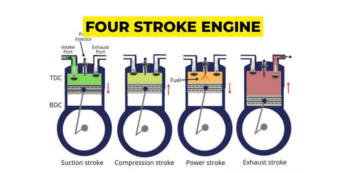
Strokes are:
- Suction: Piston moves down from TDC to BDC which will create a pressure difference in the cylinder, the inlet valve is opened and air is drawn in. During suction stroke the inlet valve is open and exhaust valve is closed. The motion of the valves is controlled by the camshaft and at the end of the stroke the inlet valve will also close.
- Compression: Piston moves from BDC to TDC and the air is compressed. During compression both inlet and exhaust valves are closed so that when the piston moves up it can compress the air. At the end of the stroke the fuel injector injects a little bit of fuel so that it will fill up the area.
- Power stroke: After compression the pressure and temperature raises that the fuel auto ignites and explosion takes place which pushes the piston toward BDC and one power stroke is generated, for every two revolutions of crankshaft there is one power stroke. Both the valves remain closed during this stroke.
- Exhaust stroke: After the power stroke the burnt gas is pushed out from the exhaust valve when the piston goes from BDC to TDC and also due to the difference of pressure between the cylinder and the atmosphere. During the exhaust stroke the exhaust valve is opened and the inlet is closed.

Parts of a four stroke engine:
Piston: It is one of the most important parts of the combustion chamber which transmits the expanding gas forces to the connecting rod therefore mechanical power can be generated because of reciprocating motion of the piston.
Function of piston: The function is same for two stroke and four stroke engines. It seals the combustion chamber, transmit gas load to the connecting rod.
Parts:
- Piston crown – it is the top part of the piston exposed to very high pressure and temperature.
- Piston skirt – lower part of the piston, which transmits side thrust to the liner in a four stroke engine.
- Piston rod – Connects piston to crosshead in two stroke engine, it is not available in four stroke engine.
Material:
- Crown – Aluminium or cast steel in four stroke engine or cast chrome nickel molybdenum alloy steel in two stroke engine.
- Shirt – Cast iron or SI Aluminium alloy
Rod- Forged steel

PISTON RINGS: There are usually 4 compression rings and 1 oil Scraper rings [ NOTE: there are no oil scraper rings in 2s engine.
COMPRESSION RINGS: Their purpose is to prevent blow past, that is to provide effective sealing of the combustion space by expanding.
OIL SCRAPER RINGS: They are fitted lowermost of the rings on the skirts in the trunk piston engine. They scrape the excessive lubricant down the liner.
Material: CAST IRON with alloys of chromium, Vanadium, titanium, molybdenum, nickel and copper.


GUDGEON PIN/ PISTON PIN/ WRIST PIN: It is the link between connecting and piston, it is only fitted in a trunk piston type engine/ four stroke engine.
Function:
- To connect piston to connecting rod
- provide bearing for the con rod, so it can move smoothly.
Material: Steel alloy of high strength and lead bronze in small engines.

Cylinder liner: Most important part of an IC engine inside which the piston reciprocates smoothly.
Function:
- Provide area for cooling, lubrication, scavenging
- Assist in sealing the combustion chamber.
Material: Pearlitic grey cast iron – contains vanadium and titanium to give strength and increase wear resistance, reducing corrosion.

CONNECTING ROD: In a two stroke engine it is fitted between cross head and crankshaft.
In a four stroke engine it is fitted between piston and crankshaft by using a gudgeon pin.
Function:
- Transmit reciprocating motion of the piston into rotary motion of the crankshaft.
- Also provide space for bearings.
Material: Mild or medium steel

CYLINDER HEAD ASSEMBLY: It is one of the most important components of combustion space, it has bore for mountings like indicator cock, inlet and exhaust valves, fuel injector, air starting valve and rocker arm assembly.
Function: To close the end of the cylinder and seal in the gases as they undergo a cycle involving extreme pressure and temperature.
Material: Head cover- cast iron

EXHAUST VALVE: The hot exhaust gas from the cylinder unit is expelled out through the exhaust valve during the exhaust cycle and further the gas goes to the exhaust manifold, they are two in number for the generator engine, while the main engine has one exhaust valve.
Material: Coating of stellite/nimonic
Exhaust valve seat: mild steel with stellite coating
Exhaust valve cage: perlite cast iron
Spindle: Nimonic

INLET VALVE: These valves are present only in four stroke engines. There are no inlet valves in the two stroke engine.
Function: These valves are opened to allow the follow of fresh air into the engine’s cylinder.
Petrol engine = air+fuel enters
Diesel engine = only air enters
Material: Seat coated with stellite
Valve is nickel based alloy
Spindle is Nimonic
Valve guide is cast iron

FUEL INJECTOR: One of the most important cylinder head mounting, which is responsible for good atomisation and penetration of the fuel.
Function: To provide the right amount of pressurised fuel at the right moment for good combustion.

INDICATOR COCK: It is one of the cylinder head mounting, which is opened for a few seconds before the fuel injection to blow out the condensate or any debris out of the cylinder.
NOTE: While engine is running it must be in shut condition
Function:
- To blow out the condensate (as liquid is incompressible, if it is not removed then it can damage the moving parts)
- Used to calculate the indicated power of the engine.

AIR STARTING VALVE: It is fitted on each cylinder head to supply 30 bars of air into the engine for cranking the engine.
Function:
- It is responsible to start the engine from standstill or stop position.
- It also helps in reversing the engine or emergency stopping(crash manoeuvring) of the engine.
Material:
Body – Mild steel
Spindle – High tensile steel
Valve seat – Stellite hardened tensile steel

CRANKSHAFT: It is a shaft, which transfers power to rotate the propeller in two stroke and to drive the alternator in a four stroke engine.
Function: Converts the oscillating motion of the con rod / reciprocating motion of the piston to rotary motion of the shaft.
Material: High carbon steel


CAMSHAFT AND CAMS: It can be of single or several units.
In two stroke engine crankshaft to camshaft ratio = 1:1
In four stroke engine crankshaft to camshaft ratio = 2:1
Function:
In two stroke engine – 2 cams per unit (to operate fuel pump and exhaust valve only)
In four stroke engine – 3 cams per unit (to operate fuel pump, exhaust and inlet valve)
Material: Hardened alloy of iron or steel.

Note
If you want to learn more about this topic, we suggest checking out our Combo package with the given link https://merchantnavydecoded.com/courses/c/ . It’s a great way to dive deeper into the subject through video explanations. This package covers all the important details and presents them in an easy-to-understand format. Watching the videos will help you grasp the topic better and make learning more enjoyable. So, we highly recommend giving our Combo package a try to enhance your knowledge on the subject.
Disclaimer :- The opinions expressed in this article belong solely to the author and may not necessarily reflect those of Merchant Navy Decoded. We cannot guarantee the accuracy of the information provided and disclaim any responsibility for it. Data and visuals used are sourced from publicly available information and may not be authenticated by any regulatory body. Reviews and comments appearing on our blogs represent the opinions of individuals and do not necessarily reflect the views of Merchant Navy Decoded. We are not responsible for any loss or damage resulting from reliance on these reviews or comments.
Reproduction, copying, sharing, or use of the article or images in any form is strictly prohibited without prior permission from both the author and Merchant Navy Decoded.


Awesome explanation
Hi,
thank you for your appreciation, we are going to upload more blogs like this please be with this blog section.
Regards
Team merchant navy decoded
Very important and simple way to teach. Thanks.