In modern industrial and marine engineering systems, signals are the foundation of communication between sensors, controllers, monitoring equipment, and automation systems. Whether measuring temperature, pressure, tank levels, or machinery status, signals carry critical information that allows operators and control systems to make informed decisions.
Signals are generally classified into two categories: Analog Signals and Digital Signals. Understanding the differences between them is essential for engineers, technicians, and engine room personnel working with automation and instrumentation systems.
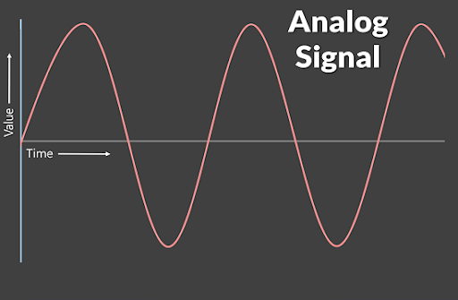
Analog Signal
An analog signal is a continuously varying signal that represents physical quantities through a range of values. The signal can take any value within a specified range and changes smoothly over time.
Table of Contents
Characteristics of Analog Signals
Continuous in Nature Analog signals vary continuously over time without sudden jumps or interruptions. Unlike digital signals, which switch between fixed states, analog signals can change smoothly and accurately reflect gradual changes in a measured parameter.
Possible Values Within Infinite a Range An analog signal can assume any value within its operating range. For example, a temperature transmitter with a 4–20 mA output can represent countless temperature values between its minimum and maximum measurement limits, providing detailed and precise information.
Represents Real-World Physical Variables Directly Most physical quantities such as temperature, pressure, flow rate, level, and speed naturally change in a continuous manner. Analog signals are well suited to represent these variables because they closely mirror the actual behavior of the measured process.
More Susceptible to Electrical Noise and Interference Since analog signals rely on continuously varying electrical values, they can be affected by electromagnetic interference, voltage fluctuations, and noise from nearby equipment. If proper shielding, grounding, and cable routing practices are not followed, signal accuracy may be compromised.
Common Transmission Standards Include 4–20 mA Current Signals The 4–20 mA current loop is one of the most widely used analog transmission standards in industrial and marine applications. It is highly reliable for transmitting measurement data over long distances and allows easy detection of wiring faults, as a current below 4 mA often indicates a circuit problem.
Common Transmission Standards Include 0–10 V Voltage Signals Voltage-based analog signals, such as 0–10 V, are commonly used in control systems and instrumentation. The measured variable is represented by a corresponding voltage level within the specified range, making signal processing relatively simple and cost-effective.
Common Transmission Standards Include Resistance-Based Signals (RTDs) Resistance Temperature Detectors (RTDs) operate by changing their electrical resistance in response to temperature variations. The resistance value is measured and converted into a temperature reading, providing accurate and stable temperature measurement for critical industrial processes and engine room applications.
A digital signal represents information using discrete values, typically binary states of 0 and 1.
Unlike analog signals, digital signals change in steps rather than continuously.
Characteristics of Digital Signals
Discrete Values Only Digital signals operate using distinct and predefined states, typically represented as binary values of 0 and 1. Unlike analog signals, which can take any value within a range, digital signals can only exist in specific states, making them easier to interpret and process by electronic devices and control systems.
High Resistance to Electrical Noise One of the major advantages of digital signals is their ability to withstand electrical noise and interference. Since digital systems only need to determine whether a signal is in a high or low state, minor disturbances in the signal do not usually affect the transmitted information. This results in more reliable communication, especially in electrically noisy environments such as engine rooms and industrial plants.
Easy to Process, Store, and Transmit Digital signals can be easily processed by microprocessors, PLCs, and computers. They can also be stored in memory devices without loss of accuracy and transmitted over communication networks with minimal degradation. This makes digital technology highly suitable for modern monitoring, control, and data logging applications.
Compatible with PLCs, Computers, and Automation Systems Modern industrial automation systems are designed to work primarily with digital data. Digital signals can be directly interpreted by Programmable Logic Controllers (PLCs), Distributed Control Systems (DCS), Human-Machine Interfaces (HMIs), and industrial computers, enabling efficient monitoring, control, and decision-making processes.
Supports Advanced Communication Protocols Digital signals form the basis of modern industrial communication networks. They can be transmitted using advanced protocols such as Modbus, CAN Bus, Profibus, HART, Ethernet/IP, and Profinet. These protocols allow multiple devices to exchange information, support remote monitoring and diagnostics, and enable the integration of complex automation systems within engine rooms and industrial facilities.
Feature
Analog Signal
Digital Signal
Nature
Continuous and varies smoothly over time
Discrete and changes between defined states
Values
Can take an infinite number of values within a specified range
Limited to distinct states, typically 0 and 1
Accuracy
Signal quality can degrade due to noise and interference
High immunity to noise, maintaining signal integrity
Transmission
More susceptible to electrical interference, especially over long distances
Reliable transmission with minimal degradation over long distances
Processing
Requires analog circuits and signal conditioning for interpretation
Easily processed by PLCs, computers, and digital controllers
Storage
More difficult to store and reproduce without loss of quality
Easy to store, copy, and retrieve without loss of information
Examples
Temperature, pressure, flow rate, tank level, speed measurements
Alarms, switch status, valve position indication, motor running/stopped signals
Applications of Analog Signals in Engine Rooms
Engine rooms rely heavily on analog signals for monitoring continuously changing process parameters.
Temperature Monitoring
Analog transmitters measure:
Main engine jacket water temperature
Lubricating oil temperature
Exhaust gas temperature
Fuel oil temperature
Pressure Monitoring
Analog pressure transmitters monitor:
Lube oil pressure
Fuel oil pressure
Starting air pressure
Cooling water pressure
Tank Level Measurement
Continuous level transmitters provide analog outputs for:
Fuel oil tanks
Lubricating oil tanks
Bilge tanks
Fresh water tanks
Flow Measurement
Flow transmitters generate analog signals for:
Cooling water circulation
Fuel consumption monitoring
Boiler feed water systems
Applications of Digital Signals in Engine Rooms
Digital signals are primarily used for status indication, alarms, and automation control.
Alarm Systems
Digital inputs are used for:
High-temperature alarms
Low-pressure alarms
High tank level alarms
Fire detection systems
Motor Status Monitoring
Digital signals indicate:
Motor running
Motor stopped
Motor trip condition
Overload condition
Valve Position Feedback
Digital limit switches provide:
Valve open indication
Valve closed indication
Safety Interlocks
Engine room safety systems use digital signals for:
Emergency shutdown systems
Generator protection systems
Boiler safety controls
Engine protection systems
Modern Engine Room Automation: Combining Analog and Digital Signals
Today’s engine rooms use both analog and digital signals together within integrated automation systems.
For example:
A temperature transmitter sends an analog 4–20 mA signal to the PLC.
The PLC continuously monitors the temperature.
If the temperature exceeds a predefined limit, the PLC generates a digital alarm signal.
The alarm activates visual and audible warning devices in the control room.
This combination provides both precise monitoring and reliable safety protection.
Disclaimer :- The opinions expressed in this article belong solely to the author and may not necessarily reflect those of Merchant Navy Decoded. We cannot guarantee the accuracy of the information provided and disclaim any responsibility for it. Data and visuals used are sourced from publicly available information and may not be authenticated by any regulatory body. Reviews and comments appearing on our blogs represent the opinions of individuals and do not necessarily reflect the views of Merchant Navy Decoded. We are not responsible for any loss or damage resulting from reliance on these reviews or comments.
Reproduction, copying, sharing, or use of the article or images in any form is strictly prohibited without prior permission from both the author and Merchant Navy Decoded.