Hi this is Team Merchant Navy Decoded !!!

Please fill the below form with your query and we will get back to you in next 12 hours.

Rest assured your data is safe with us !!!🙂

Ask Your Query

Electric Motor Maintenance Procedure

Electric Motor Maintenance Procedure

Every ship runs on dozens of electric motors quietly doing work nobody thinks about until one stops  pumps, fans, purifiers, steering gear, winches. Most of them never get a dramatic failure. They degrade slowly, and the whole point of a proper maintenance procedure is catching that decline with a meter and a logbook, long before it shows up as a tripped breaker or a burnt winding.

This post covers the full picture: routine checks, the two instruments that actually tell you the motor’s real condition, how to safely dismantle one, and the precautions that matter throughout.

Routine Checking

Routine Checking

Before any instrument comes out, a motor tells you a lot just from a walk-by inspection.

Weekly / routine watch checks:


  • Listen for unusual noise – Grinding, humming, or a change in pitch from normal running
  • Feel (or check via installed sensors) for excessive vibration
  • Check bearing temperature, either by hand on the housing or via a fitted temperature sensor
  • Look for oil or grease leakage at the bearing housings
  • Confirm cooling air paths and fan covers are clear of dust, lint, or debris
  • Check terminal box condition – Tight connections, no signs of overheating or discoloration
  • Note running current on the ammeter if the motor is running under load, and compare against its rated value


Periodic checks (per planned maintenance schedule):


  • Insulation resistance testing (megger test )
  • Bearing grease replenishment or renewal, per the manufacturer’s interval
  • Terminal box and cable gland inspection for moisture ingress
  • Earthing/grounding connection check
  • Full dismantling and internal inspection at longer intervals, or when test results indicate a problem

A motor that fails a routine check isn’t automatically due for a teardown  but a motor that’s never actually been checked has no baseline to compare a bad reading against, which defeats the purpose of testing at all.

Megger Test (Insulation Resistance Test)

This is the single most important electrical test performed on a motor, and it’s testing something a visual inspection simply can’t see: the condition of the winding insulation itself.

What it actually measures: the resistance between the motor’s windings and earth (and between windings phase-to-phase), using a megohmmeter, a “megger”  that applies a DC test voltage and measures the tiny leakage current that gets through. Lower leakage current means higher, healthier insulation resistance.

Before testing – isolation comes first, always:

  1. Stop the motor and isolate it electrically at the switchboard or starter
  2. Lock out and tag the isolation point
  3. Disconnect the motor’s cable from the starter/supply side, so only the motor windings themselves are being tested, not the whole circuit
  4. Disconnect any space heaters, thermistors, or surge protection devices from the terminals  these provide a parallel path that gives a falsely low reading if left connected
  5. Confirm nobody is in contact with the motor or its terminals before applying test voltage

Test procedure:

  1. Connect the megger leads – One to a winding terminal, one to earth (motor frame)
  2. Apply the test voltage – Commonly 500V DC for motors rated up to 440V, higher for higher-voltage motors
  3. Take readings between each phase and earth (U-E, V-E, W-E) and between phases (U-V, V-W, W-U)
  4. Record every reading, along with the winding temperature at the time of test, since insulation resistance varies with temperature and a reading taken hot isn’t directly comparable to one taken cold without correction
  5. Discharge the winding (short it to earth) after the test before reconnecting anything  a winding can hold residual charge after a megger test

Reading the results:

Insulation resistance 

Condition

Below 1 MΩ

Bad – High risk of failure

1-10 MΩ

Marginal/ abnormal 

10-50 MΩ

Good 

50-100 MΩ

Very good 

Above 100 MΩ

Excellent 

A commonly used rule of thumb for the minimum acceptable value: 0.5 MΩ per kV of rated voltage, plus 1 MΩ though the exact figure a specific PMS or class requirement calls for should always take precedence over a general rule.

The Polarization Index (PI) test takes this further, for larger motors especially. Instead of one reading, resistance is recorded at 1 minute and again at 10 minutes under the same continuous test voltage, and the PI is the ratio between them:

PI = (10-minute reading) ÷ (1-minute reading)

A PI below 2.0 suggests contaminated or moisture-affected insulation, even if the absolute resistance reading looks acceptable on its own  which is exactly why PI is considered a more reliable diagnostic than a single spot reading, especially for catching a problem that a one-off measurement would miss entirely.

One reading is a snapshot. A logged trend is the real diagnostic tool. The value of megger testing comes from comparing today’s reading against last month’s and last year’s for the same motor  a gradually falling trend flags a developing problem long before any single reading crosses into “bad” territory.

Table of Contents

Multimeter Checks

Where the megger tests insulation condition, the multimeter checks the motor’s basic electrical health continuity, resistance, and voltage, all with the motor isolated and de-energized unless a live check is specifically required and properly risk-assessed.


Common multimeter checks:


  • Winding continuity – Confirm each phase winding shows continuity end to end, ruling out an open circuit within the winding
  • Winding resistance balance – Measure resistance across each of the three windings (U-V, V-W, W-U) and compare them; a healthy three-phase motor should show close to identical resistance across all three, and a noticeably unequal reading points to a developing winding fault
  • Earth continuity – Confirm the motor frame and earthing point show a genuine, low-resistance connection to earth, not an open or high-resistance path
  • Supply voltage and current (when running) – Confirm the motor is actually receiving balanced voltage across all three phases, and that running current sits within its rated range rather than creeping upward, which often signals a mechanical problem (bearing drag, misalignment) rather than a purely electrical one

Multimeter checks and megger checks aren’t substitutes for each other; a motor can pass a continuity check with flying colours while its insulation resistance is quietly failing, and vice versa. Both tests are checking genuinely different things.

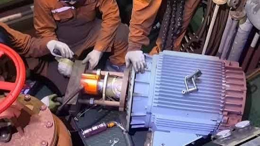
How to Dismantle a Motor

Dismantling only happens once electrical isolation and lockout are already confirmed never as a shortcut past that step.

Sequence:

  1. Isolate, lock out, and tag the motor’s power supply, and verify zero voltage with a tested meter before touching anything
  2. Disconnect and label all terminal connections, noting wire positions for correct reassembly
  3. Remove the coupling or belt drive connecting the motor to its driven equipment
  4. Support the motor properly before removing its mounting bolts  motors are heavier than they look, and an unsupported motor coming free of its mounts is a genuine crush hazard
  5. Remove the end shields (bearing covers) at both drive and non-drive ends
  6. Carefully withdraw the rotor from the stator, supporting its weight throughout — never let the rotor drag or scrape against the stator windings on the way out, since this can gouge the winding insulation
  7. Inspect and remove bearings using a proper bearing puller, never a hammer and chisel directly on the bearing race
  8. Clean and inspect the stator windings, rotor, and bearing housings before proceeding to any repair or reassembly

During inspection, check specifically for:

  • Discoloration or a burnt smell on the windings, indicating overheating
  • Cracked, brittle, or flaking winding insulation
  • Bearing wear, pitting, or discoloration from overheating
  • Rotor bar condition on induction motors, and any sign of rubbing between rotor and stator
  • Cleanliness of cooling air paths and fan blades

Reassembly follows the same sequence in reverse, with a few points worth treating as mandatory: fit new bearings if there’s any doubt about the old ones’ condition rather than reusing a borderline bearing, torque end shield bolts evenly and in sequence, and rotate the rotor by hand once reassembled to confirm it turns freely before reconnecting power.

Drying Out a Damp or Low-Reading Motor

A motor that fails its megger test isn’t automatically scrap  moisture is a genuinely common, reversible cause of a low reading, and it’s worth ruling out before condemning the winding.

How to tell moisture is the likely cause: a low insulation resistance reading combined with a poor Polarization Index, especially after the motor’s been idle for an extended period, sitting in a humid engine room, or recently exposed to a leak or flooding event nearby.

Common drying methods:

  • Space heaters, where fitted, run continuously at low power specifically to keep the motor slightly warm and prevent moisture accumulation during idle periods  this is a preventive measure as much as a cure
  • External heat lamps or a low-temperature oven for smaller motors removed for drying, keeping winding temperature within the insulation class’s safe limit rather than applying heat aggressively
  • Low-voltage current drying, sometimes called “cooking” the windings, passing a reduced current through the stator to generate gentle internal heat and drive moisture out from within, rather than only from the outside in
  • Extended ventilation and time, simply leaving the motor open and well-ventilated in a dry space, for less urgent cases

Whatever method is used, insulation resistance should be re-tested periodically during the drying process rather than assumed to have recovered  the readings themselves tell you when drying has actually worked, not a fixed time estimate.

Common Causes of Motor Failure

Recognising the likely cause behind a bad reading or a physical fault helps decide whether the fix is genuinely a repair job or a straightforward renewal.


Symptom 

Likely Cause 

Gradually falling insulation resistance over successive tests

Moisture ingress or slow insulation ageing

Sudden, sharp drop in insulation resistance 

Physical winding damage, contamination or a developing short

Unbalanced winding resistance across phases

Localised winding fault or a loose internal connection 

Overheating with no electrical fault found 

Blocked cooling air path, failing bearing or sustained overload 

Bearing noise or vibration 

Worn bearing, misalignment with driven equipment 

Frequently tripping on starting 

Voltage imbalance, a stuck rotor or a failing starter component 

Re-Commissioning After Maintenance

Re-Commissioning After Maintenance

Once a motor’s back together, putting it straight back into full service isn’t the right last step; a short, deliberate re-commissioning sequence catches problems while they’re still cheap to fix.

  1. Confirm megger and multimeter checks both pass before applying power at all
  2. Rotate the shaft by hand to confirm free movement with no unusual resistance or noise
  3. Run the motor uncoupled from its load first, where practical, checking for correct rotation direction, smooth running, and normal current draw at no load
  4. Couple to the driven equipment only once the uncoupled run looks clean
  5. Bring the motor up to full load gradually, monitoring current balance across all three phases and bearing temperature as load increases
  6. Log the post-maintenance megger reading and running parameters as the new baseline for future trend comparison

Skipping straight to full-load running after a repair is one of the more common ways a small, missed issue turns into a repeat failure within days rather than being caught during a five-minute uncoupled test run.

Safety Throughout

Electric motor work carries two separate hazard categories, and both need respecting at once  electrical and mechanical.

  • Isolate, lock out, and verify dead before any work begins  never rely on a switch position alone; test with a meter known to be working
  •  Treat a megger-tested winding as potentially charged until it’s been properly discharged to earth after the test
  • Never couple a motor to its load, or apply power, with the terminal box open or connections incomplete
  • Support the motor’s weight properly during dismantling  a motor coming free unexpectedly from its mounts is a genuine injury risk, not just an inconvenience
  • Use the correct tools for bearing removal  a bearing puller, not a hammer, avoids damaging the shaft or housing
  • Keep the work area dry and clean, particularly important given how sensitive insulation resistance readings are to moisture contamination
  • Confirm free rotation by hand before restoring power after any reassembly  a rotor that doesn’t turn freely means something is still wrong, and running it anyway risks turning a simple fix into a real failure

Conclusion

An electric motor’s outward health and its actual electrical condition are two different things, which is exactly why routine checks, megger testing, and multimeter checks all exist together rather than any one of them standing in for the others. A quiet, smooth-running motor can still be carrying insulation that’s quietly failing and the only way to know is to actually test it, log the result, and watch the trend rather than judging a motor purely by how it sounds. Isolate properly, test methodically, dismantle carefully, and a shipboard motor will keep doing its unglamorous, essential job for years between overhauls.

Frequently Asked Questions (FAQs)

A megger measures insulation resistance by applying a DC test voltage (commonly 500V) and reading the tiny leakage current through the winding insulation to earth. A standard multimeter isn’t designed to apply that test voltage or measure resistance in the megohm range accurately, which is why the two instruments check genuinely different things.

The most important parameters include sulphur, water, viscosity, density, aluminium plus silicon, vanadium, sodium, flash point, total sediment, carbon resi

As a general guide, readings above 10 MΩ are considered good, with a common minimum acceptable threshold calculated as roughly 0.5 MΩ per kV of rated voltage. Readings below 1 MΩ indicate a high risk of failure. The exact figure required by the vessel’s PMS or class requirements should always take precedence over a general rule of thumb.


due and CCAI. These values help identify risks such as abrasive wear, poor combustion, corrosion, sludge formation and regulatory non-compliance.

The Polarization Index is the ratio of the insulation resistance reading taken at 10 minutes to the reading taken at 1 minute, under the same continuous test voltage. A PI below 2.0 can reveal contaminated or moisture-affected insulation even when the absolute resistance value looks acceptable on its own, making it a more reliable diagnostic than a single spot reading.

These components provide a parallel electrical path alongside the winding insulation itself. Left connected, they can produce a falsely low insulation resistance reading that doesn’t accurately reflect the actual condition of the winding insulation.


Isolating and locking out the power supply, then verifying zero voltage with a tested meter before touching any part of the motor or its terminals never relying on a switch position alone as confirmation that the supply is actually off.

Disclaimer :- The opinions expressed in this article belong solely to the author and may not necessarily reflect those of Merchant Navy Decoded. We cannot guarantee the accuracy of the information provided and disclaim any responsibility for it. Data and visuals used are sourced from publicly available information and may not be authenticated by any regulatory body. Reviews and comments appearing on our blogs represent the opinions of individuals and do not necessarily reflect the views of Merchant Navy Decoded. We are not responsible for any loss or damage resulting from reliance on these reviews or comments.

Reproduction, copying, sharing, or use of the article or images in any form is strictly prohibited without prior permission from both the author and Merchant Navy Decoded.

DIWALI SALE

Decoded Discount Alert! up to 50% OFF

DIWALI SALE

Decoded Discount Alert! up to 50% OFF

Use Coupon Code Deep50

Days
Hours
Seconds
0
Would love your thoughts, please comment.x
()
x