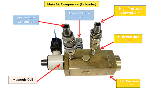
The unloader is a solenoid-operated, spring-loaded valve arrangement fitted at the end of the drain lines coming from the intercooler and aftercooler.
Purpose of Unloader
Restriction of starting Current in the motor,as we know the starting current is five times the rated current of the motor,it must be unloaded,to prevent the motor from being overloaded.
The Compressor draws air from the engine room,where air is not dry and mixed with moisture and oil,this oily mixture can damage the compressor parts like piston ,valves etc.Hence should be drained at regular intervals.
At Stopping the same is done so as to drain all the moisture inside and in operation for next starting.
Intermittently the compressor is unloaded to remove the condensed water inside,which could go outside with air.
Table of Contents
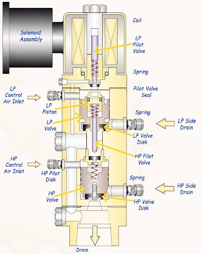
Construction of Main air compressor Unloader
Solenoid Assembly
This is the electrical operating part of the unloader. When power is given, the solenoid coil creates magnetic force and moves the LP pilot valve stem downwards.
It controls whether the unloader is in loaded or unloaded condition
LP Pilot Valve
This is the small control valve for the LP unloader section.
It controls the LP control air path. It does not directly handle large compressor air flow; it controls control air, which then operates the LP valve.
LP Control Air Inlet
This is the control air supply entering the LP side which works along with Solenoid valve assembly which operates the LP Pilot valve to keep the LP Valve closed ,when the compressor is running.
LP Piston
The LP piston receives control air pressure.
When control air pressure acts on it, it moves and operates the LP valve disk.
LP Valve
This is the actual unloading valve for the low-pressure side.
When open, it drains LP side air through the LP side drain. When closed, LP compression air goes normally toward the next stage intercooler.
LP Side Drain
This is the drain path for the LP side.When the LP unloader opens, trapped LP stage air is released from here.
HP Pilot Valve
This is the small control valve for the HP unloader section
It controls the HP control air path and operates the HP unloading valve.
HP Control Air Inlet
This is the control air supply entering the HP side.
It provides control air pressure to operate the HP valve and keep it in closed position,when the compressor is running.
HP Valve
This is the actual unloading valve for the high-pressure side.
When open, it drains HP side compressed air through the HP side drain. When closed, HP compression air goes normally towards the air receiver.
HP Side Drain
This is the drain path for the HP side.
It releases trapped HP side air when the HP unloader opens
Springs
There are springs in the pilot valve and valve disk sections
Springs return the valves to their normal position when solenoid force or control air pressure is removed. They also help keep valve disks seated properly.
Common Drain at Bottom
++The bottom drain releases air,water,oil mist from the unloading arrangement.
As discussed Above the unloader is operated at starting ,stopping and intermittent phase
The Starting Phase
As soon as the main air compressor receives a start command, the control panel instantly energizes the unloader solenoid valve, forcing it to open. It remains in this open state for 5 to 10 seconds while the motor starts,to prevent the motor from being overloaded.
Sequence of operation
Lp control air reaches into the unloader and pushes the LP piston downwards and simultaneously Solenoid assembly is in de-energize condition so the Lp pilot valve moves upwards due to the spring force and such that air passes through the aperture hole and then drain to bilges.
At the same time Hp control air reaches into the unloader and air pass through the aperture hole and drains to the bilges
Now once the compressed air is received,it will drain to the bilges through the common drain at bottom by lifting the valves.
So Compressed air from LP and HP sides drain lift up respective Lp and Hp valves and then drain to the bilges through the common drain.
The Stopping Phase
vents any residual high-pressure air trapped within the compressor stages and clears out the last remnants of condensed moisture. Purging this moisture prevents internal corrosion from setting in while the machinery stands idle, and completely vents the internal pressure so that the compressor is perfectly primed for a safe, low-load restart when the next demand cycle triggers.
Sequence of operation
LP pilot valve is opened by spring upward force and the path is restricted by Lp piston as there is no control air supply.
LP valve is closed by its own weight
HP pilot valve is opened by spring upward force.
Hp valve is closed by its own weight and spring force.
In the event of Tube Leaking
Water pressure lifts up the respective valves as the water force is higher than the spring force and drain into the bilges
The Intermittent Phase
Once the compressor is actively compressing air, it switches to an automated cyclical routine. The unloader valve closes to allow pressure to build, but a timer in the control panel simultaneously begins counting down.
At fixed, regular intervals during operation, the control panel momentarily re-energizes the solenoid to open the unloader for 5 to 10 seconds before closing it and resetting the timer for next interval till it reaches the set point again,this draining of air takes place continuously till the compressor is running.
The air drawn from the engine room contains a high volume of humidity and suspended oil mist. As this air is squeezed into a smaller volume, these vapors rapidly condense into a corrosive, sludgy liquid mixture.
Periodically opening the valve blows this accumulated oil-water condensate out of the intercooler and aftercooler stages. This prevents the liquid from migrating into the cylinders where it could cause severe mechanical damage to the pistons and valves and ensures clean, dry air is delivered to the ship’s air receivers.
Sequence of operation
Solenoid Energize and Lp pilot valve moves downwards restricting the path through the aperture hole
Lp control air pressure starts acting on the LP piston leading to close the LP valve by pushing it down, simultaneously causing the HP pilot valve to shut.
Hp Control air pressure starts acting on the Hp valve to keep it in closed position.
No more drain from Hp and Lp sides.
Maintenance of unloader
Over time, the constant carryover of moisture and oil creates a thick, sticky sludge. Dirt accumulates inside the valve body, causing the internal mechanisms to become sluggish,leading the unloader to be stuck at open or close position.
Periodically overhauling the solenoid valve block. Cleaning the spring, piston, and valve seats with an appropriate degreasing solvent is necessary.
Disclaimer :- The opinions expressed in this article belong solely to the author and may not necessarily reflect those of Merchant Navy Decoded. We cannot guarantee the accuracy of the information provided and disclaim any responsibility for it. Data and visuals used are sourced from publicly available information and may not be authenticated by any regulatory body. Reviews and comments appearing on our blogs represent the opinions of individuals and do not necessarily reflect the views of Merchant Navy Decoded. We are not responsible for any loss or damage resulting from reliance on these reviews or comments.
Reproduction, copying, sharing, or use of the article or images in any form is strictly prohibited without prior permission from both the author and Merchant Navy Decoded.
START YOUR LEARNING JOURNEY
Fill in the form to access MND FLIX and get expert guidance.